Saturday, June 15, 2019

View Orbit in Autodesk Fusion 360

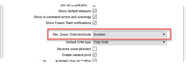
There are three methods you can use to orbit your model in Autodesk Fusion 360.  If you have your Pan, Zoom, Orbit shortcuts set to "Inventor", you have a fourth method.

 In my short video, I cover these methods and explain options associated with each one.


Friday, March 22, 2019

Creating Conical Sheet Metal Components

Autodesk Fusion 360 does not provide a method for making conical sheet metal components but with the available tools and a little bit of surface work, the process can accomplished easily.  In this short video I first create a simple sheet metal cone with its flat pattern.  I then go back, in the timeline, and show you how to used the process to make a truncated cone that will produce a square edged flat pattern.

A special thanks to "TheCADWhisper", also known as "Top Daug" from the Fusion 360 forum for giving me inspiration into the methods outlined in this article.

UPDATE: Fusion 360 has added a new tool called Lofted Flange which makes the creation of a sheet metal cone very easy.  In this video I go over the process of using this tool.  If you desire to create an angled truncated cone, the process is also outlined in the video as it is a little different than the method outlined above.


Thursday, March 14, 2019

Creating Component Structure in Autodesk Fusion 360

Components are the building blocks of Autodesk Fusion 360 assemblies and sub-assemblies.  Sooner of later you must create components from your sketches and bodies in order to use joints to create an effective assembly.   There are four methods of creating components which I cover in a short video, all but the final method will work effectively.  The ideal structure of a component is to have all bodies and their related sketches located under the component not split between the top level assembly and components.  Below is a good example of this proper structure.

Saturday, March 2, 2019

Components and Their Applied Joints

I have heard many users of Autodesk Fusion 360 ask the question "How do I determine which components my assembly joints are applied to AFTER the assembly is finished?"  Face it, we are all a bit lazy and probably do not do a good job of identifying our assembly joints by name or description.  We find ourselves hunting around the joints folder trying to find the correct joint to edit or modify.

I have created a short video showing the process of determining what components are used by an assembly joint and vice versa determining the joint(s) applied to an assembly component.  I also talk about how to manipulate the graphic display to better show your results.


Thursday, February 7, 2019

Applying Autodesk Fusion 360 Pin - Slot Joints

Of all the Autodesk Fusion 360 assembly joints, the Pin - Slot joint probably gives users the most trouble creating and controlling.  In this video, I point out some of the conditions for using Pin - Slot joints and also show how to set the joint limits in a simple assembly.


Monday, January 28, 2019

Creating and Using Drilling Templates in Autodesk Fusion 360

Designers use may standard components in their designs each day and often they have to be mounted into an assembly.  This requires the drilling of mounting holes that match the standard component.  Most designers would place the standard component into the assembly and then create the required holes, for bolting or component clearance, directly from the component.  In my video I propose the use of a saved drilling template which can be used to create all the necessary holes for the standard component mounting WITHOUT the standard component.  This method has a few advantages.
  • Speed - Placing a template in position and then simply placing holes according to template is a lot faster than trying to place a standard component in place in order to determine hole centers
  • Accuracy - A drilling template cuts down on possible hole placement errors.  Not only will the drilling centers be located in the drilling template but hole sizes can be specified also.
  • Easy of Placement - It is a lot easier to locate a drilling template, as a sketch, than the actual standard component in the assembly using joints
  • Create the Final Part without the Standard Component - If you wish, you can place a drilling template on a part to locate all mounting holes without every having to create an assembly model.
One warning about using this method, it has two "quirks" that you must be aware of to use it effectively.  They are easy to understand and workaround and I illustrate them in the video.


Thursday, January 17, 2019

Procedure and Considerations When Using "Insert a Manufactured Part" Command in Autodesk Fusion 360

The ability to select and insert thousands of parts and assemblies of numerous companies from around the world is a real time saved in Autodesk Fusion 360.  I have created a video outlining the process and also included some tips to create a functional model for your design.