Tuesday, August 29, 2017
Autodesk Fusion 360 Sketching Tips and Techniques
The sketching environment in Autodesk Fusion 360 contains many functions and techniques that are not always apparent. I have created a short video to show you some of my favorite ones in the hope to give a quick start into using a new sketching function or discover one you just did not know existed.

Monday, August 21, 2017
Autodesk Fusion 360 Viewports
Autodesk Fusion 360 Viewports give you the ability to setup special views which can be used for functions such as sketching, assembly work, sectional analysis and many others. Named viewports can be saved with your design for use at anytime during the design process. I will use one of the sample parts to demonstrate some of the uses and configurations of viewports using a short video.


Friday, August 18, 2017
Inventor 2018 Hole Annotation - It's Your Choice
Autodesk introduced Model Based Dimensions (MBD) for part models in the 2018 release and for assembly models in the 2018.1 update for subscription customers. If you have used this new functionality you have found it to be lacking is a some areas and the operation needs to be polished in others. If you agree with me, take a look at this Inventor Ideas post and give it a "Vote Up".
This article is to demonstrate two methods of applying Hole/Thread Notes to a part model with my main focus on how to overcome the lack of the hole count being included in the call out. This is a standard function in the 2D drawing and it should be added for all multiple hole call outs in the part model. My sample part consist of multiple holes and types. Some of the holes are patterns which some are simple placed on multiple sketch points.


This article is to demonstrate two methods of applying Hole/Thread Notes to a part model with my main focus on how to overcome the lack of the hole count being included in the call out. This is a standard function in the 2D drawing and it should be added for all multiple hole call outs in the part model. My sample part consist of multiple holes and types. Some of the holes are patterns which some are simple placed on multiple sketch points.

The first method is to use the "Hole/Thread Note" command and manually add the hole count during placement. This method requires you to know the total number of holes of the type you are placing the note. The application will not count them for you. This means if you have similar types of holes, you will have to be sure and count accurately. For example if there were four (4) 1/4" drill holes and two (2) 17/64" drill holes you may have a hard time telling them apart to get an accurate count especially if you did not create the part.
After selecting the hole and placing the call out, the configuration dialog is displayed. Select the indicated icon to bring up the Edit Hole Note dialog box.

You will notice that the "Hole Count" icon is unavailable. Position your cursor on the hole text and type in your desired count indicator. Select "OK" to return to the hole configuration screen, verify and then place the hole note on the model.


The second method requires a little more hole note configuration but it has the advantage of placing the hole count automatically on the hole note. You will be using the "Tolerance Feature" command to place hole notes. The first tolerance feature you need to place is a "datum" on the surface the holes originate from. When selecting the type of tolerance feature to place use the "Planar Surface" note, it is the simplest. I will be hiding this note anyway.

I next will select this tolerance note in the browser and turn off the visibility. This is your choice but since all I needed to establish was a datum surface, I can turn it off. Next select the "Tolerance Feature" command and select a hole. If there are more than one hole of the type you selected, it will highlight them all and give you a list of the arrangement it found. I selected a counter-bored hole, one of four, and in the drop down list, I will choose "Multi-Element Hole Parallel Axes Pattern" to pick up the clearance hole and the counter-bored hole. These selections will vary depending on the type of hole you select.

Next, I will select the "OK" icon. Because this is a counter-bored hole, the command will prompt me to select the "Reference Feature". Select the face you earlier place the datum surface which is the same surface the holes were place on.

Once you do this, you can place the hole note and bring up the hole note configuration screen.

The next steps are optional depending on the information you wish to display. I do not want the datum to show so I will un-check the "datum" icon.

I do not want the GD&T call out so left click on the GD&T position symbol and then select "Remove Feature Control Frame". Last I select "OK" or "+" if I need to add more hole call outs.

Even though this method is a little more work, it automatically counts the number of similar holes on the face. Also, if you go back and select the hole call out, all the matching holes are highlighted in the model.

I am hoping Autodesk will add this hole counting feature to the "Hole/Thread Note" command in a future release or update.
Thursday, August 17, 2017
Exploring the Autodesk Fusion 360 Sheet Metal Environment
The Autodesk Fusion 360 sheet metal environment only has one command so it seems to be limited in its functionality. I have found that you can do a lot more than I first thought using the "Flange" tool. I have also learned that combining the modeling environment with the sheet metal environment also adds a great deal of functionality.
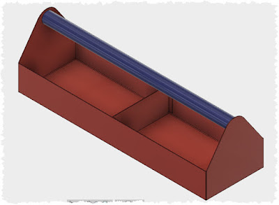
I created a short video to help show off some of this functionality. I will be creating a small sheet metal tray with one divider as my model. The handle is just a piece of pipe so it will not be included in the demonstration. You will find the video by clicking here.
I created a short video to help show off some of this functionality. I will be creating a small sheet metal tray with one divider as my model. The handle is just a piece of pipe so it will not be included in the demonstration. You will find the video by clicking here.

Friday, August 11, 2017
Creating Sheet Metal Components in Autodesk Fusion 360
Autodesk has recently released an update to Fusion 360 which includes a sheet metal modeling environment. When designing sheet metal assemblies it is often advantageous to create parts in the context of existing parts. As you create your sheet metal parts within the same file, you will want to make them components instead of bodies since assembly joints cannot be placed between bodies.
There is only one tool in the Sheet Metal environment called "Flange" and is used to create Face, Flange and Contour Flange features from your sketch or model. If you select an open sketch, the tool will create a Contour Flange. If you select a closed sketch, the tool will create a Face. If you select an edge of an existing sheet metal component or body, it will create a flange.
 When creating either a Face or Contour Flange, the dialog box gives you the opportunity to create the operation as a "New Body" or a "New Component". Below are these Flange dialog boxes during the creation of a Face, from a closed sketch, and a Contour Flange from an open sketch. NOTE: I could not get the drop-down to function and capture the screen together.

 My reason for writing this article is that if you forget to change the "Operation" to "New Component" you cannot from to the timeline, edit the Flange feature and change the operation result from New Body to New Component. The option is not available in the Edit Feature dialog box.

If you notice it right away, you can use the "Undo" command and re-create the Flange feature using the New Component option. But what do you do if you have moved forward and cannot effectively "Undo" a lot of work. You first thought may be to select the sheet metal body in the Browser, right click and select "Create Components from Bodies" command from the context menu.
 If you do, you will be met with an unpleasant warning from Fusion 360 that the operation is not supported for sheet metal bodies.

I have not found a method of converting a sheet metal body to a sheet metal component capable of being edited in the Fusion 360 sheet metal environment. Since the "Flange" tool defaults to the operation of creating a "New Body" be careful. The only work around is to "Delete" the Flange feature from the timeline and recreate it. I have not explored all the ramifications for this in a large sheet metal project.I will definitely be adding this to the Fusion 360 wishlist.
There is only one tool in the Sheet Metal environment called "Flange" and is used to create Face, Flange and Contour Flange features from your sketch or model. If you select an open sketch, the tool will create a Contour Flange. If you select a closed sketch, the tool will create a Face. If you select an edge of an existing sheet metal component or body, it will create a flange.


If you notice it right away, you can use the "Undo" command and re-create the Flange feature using the New Component option. But what do you do if you have moved forward and cannot effectively "Undo" a lot of work. You first thought may be to select the sheet metal body in the Browser, right click and select "Create Components from Bodies" command from the context menu.


I have not found a method of converting a sheet metal body to a sheet metal component capable of being edited in the Fusion 360 sheet metal environment. Since the "Flange" tool defaults to the operation of creating a "New Body" be careful. The only work around is to "Delete" the Flange feature from the timeline and recreate it. I have not explored all the ramifications for this in a large sheet metal project.I will definitely be adding this to the Fusion 360 wishlist.
Thursday, August 10, 2017
Creating Sheet Metal Flat Pattern of Round Object in Autodesk Fusion 360
Update (9/19): The method shown below is not required to create a flat pattern of a cylindrical component in the latest version of Fusion 360. Selecting on the inside or outside face of the cylinder, as the stationary face, is now all that is required. If you desire to use the Unfold tool, the method outlined in the blog and video still must be used.
----------------------------------------------------------------------------------------------------------- Autodesk recently released an update to their Fusion 360 application. This update contained many wonderful enhancements and new features, one of these was the long awaited sheet metal environment. The sheet metal environment is very versatile and can make most sheet metal forms and the flat patterns needed to fabricate them.
There is one exception to creating a flat pattern and that is for cylindrical objects such as the sheet metal part below. If you are wondering how to make the part with only the "Flange" command, apply it to an arc creating what you call a contour flange in Inventor.
 Fusion 360 "Create Flat Pattern" command requires a flat surface along the surface to be unfolded. Since this cylinder does not have one, you cannot execute the command on it. The solution is to add a very small flat to the edge of the cylindrical surface. I have created short video to illustrate this process. Click the LINK to view.
By the way, this same technique can be the used with the "Unfold" tool as well. Enjoy.
----------------------------------------------------------------------------------------------------------- Autodesk recently released an update to their Fusion 360 application. This update contained many wonderful enhancements and new features, one of these was the long awaited sheet metal environment. The sheet metal environment is very versatile and can make most sheet metal forms and the flat patterns needed to fabricate them.
There is one exception to creating a flat pattern and that is for cylindrical objects such as the sheet metal part below. If you are wondering how to make the part with only the "Flange" command, apply it to an arc creating what you call a contour flange in Inventor.

By the way, this same technique can be the used with the "Unfold" tool as well. Enjoy.
Friday, August 4, 2017
Replacing Content Center Family Template
Creating custom Inventor Content Center Libraries (CCL) is one method of configuring an existing CCL to match the standards of your company. You can add an ERP number, change the part number so the parts list reflect your naming standards or editing out all the entries you just do not need. I know one company that removes all of the fine thread fasteners from their custom ANSI socket head cap screw library. This article will outline the process of replacing the family template of a custom CCL.
First of all what does replacing the family template do. Well it all depends on your imagination. Basically any parametric feature(s) and property change or addition can be added to all the members in one quick operation. Below are three examples. The structural angle is configured with parametrically controlled holes on both legs. In one library a standard ANSI library CCL was copied and a parametric pin end was added and in another one the dull battleship gray color was changed to polished gunmetal. Keep in mind that all these additions were made to a custom CCL in just one click for every member of library.
 I will be using the addition of the pin end to a standard CCL as my example. All the steps from this point on required you to have CCL administrative rights. I will be using an Inventor desktop CCL but a Vault CCL would follow the same process. The first step is to create a read-write CCL to created your custom CCL within. This is done from the Inventor Project file manager.

Next step will be to make a copy of the standard CCL I will be modifying into my custom CCL BtDB. This is done in the CCL editor which is found under the Tools tab, Content Center panel if you do not have a file open. You can also find it under the Manage tab if you have a file open.

In the Editor, find the standard CCL you want to copy. In my case, I am using the ANSI Hexagon Socket Head Cap Screw - Inch. Right click on the library and choose "Save Copy As..
 In the Save Copy As dialog box, make sure you are creating an "Independent family". Fill out the other fields to suit you needs. Below are my entries, just make sure they are unique. If you have more than one custom CCL also be sure to select the one you want to publish to in the first field. Select "OK" to continue and start the copy.

Navigate to the new Library View and right click on the custom CCL you just created. Select "Family Properties" from the context menu.
 This step is optional but I highly recommend it in order to make easier to manage and search for your custom CCL. Fill in the three marked fields with your company name or abbreviation. Select "OK" to finish and then "Done" in the lower right corner of the Content Center Editor to exit the application.
The next step is to create one custom part from you new CCL to parametrically modify. This is done by simply placing a custom CCL part from you new library into an assembly and saving it with a special name. In my case since I am adding a parametric pin end, I want to create the smallest screw in the library so my parameters will fit all larger members of the library. I deleted a lot of screws, which my company does not use, so the smallest screw is a #8. I will choose a #8 x 1" LG since I want some length to work with.

The next step is to add the parametric pin to the saved screw making sure to give the parameters descriptive names to make it easier to edit later during placement. Below are my three parameters. At this point you can add an iLogic global form to help with the sizing of the screw, this is purely optional. Once finished, save and close the file.

The last step is to apply the parametric part to the entire custom CCL which will add the parametric features and any modified or custom properties. Open up the Content Center Editor from the Tools tab as you did before and navigate to your custom CCL library entry. Right click on it and select "Replace Family Template" from the context menu.
 Browse to your parametric part you just saved and then select "Open" to continue. Be patient at this point and wait for the following dialog to appear. You may receive a warning about a style library mismatch, just select "OK" to move forward.

You are all done. Open up an assembly and try out your handiwork. Remember, if you place a larger screw than the template part, it will look strange until you edit the parameters to suit. Enjoy.

First of all what does replacing the family template do. Well it all depends on your imagination. Basically any parametric feature(s) and property change or addition can be added to all the members in one quick operation. Below are three examples. The structural angle is configured with parametrically controlled holes on both legs. In one library a standard ANSI library CCL was copied and a parametric pin end was added and in another one the dull battleship gray color was changed to polished gunmetal. Keep in mind that all these additions were made to a custom CCL in just one click for every member of library.


Next step will be to make a copy of the standard CCL I will be modifying into my custom CCL BtDB. This is done in the CCL editor which is found under the Tools tab, Content Center panel if you do not have a file open. You can also find it under the Manage tab if you have a file open.

In the Editor, find the standard CCL you want to copy. In my case, I am using the ANSI Hexagon Socket Head Cap Screw - Inch. Right click on the library and choose "Save Copy As..


Navigate to the new Library View and right click on the custom CCL you just created. Select "Family Properties" from the context menu.

The next step is to create one custom part from you new CCL to parametrically modify. This is done by simply placing a custom CCL part from you new library into an assembly and saving it with a special name. In my case since I am adding a parametric pin end, I want to create the smallest screw in the library so my parameters will fit all larger members of the library. I deleted a lot of screws, which my company does not use, so the smallest screw is a #8. I will choose a #8 x 1" LG since I want some length to work with.

The next step is to add the parametric pin to the saved screw making sure to give the parameters descriptive names to make it easier to edit later during placement. Below are my three parameters. At this point you can add an iLogic global form to help with the sizing of the screw, this is purely optional. Once finished, save and close the file.

The last step is to apply the parametric part to the entire custom CCL which will add the parametric features and any modified or custom properties. Open up the Content Center Editor from the Tools tab as you did before and navigate to your custom CCL library entry. Right click on it and select "Replace Family Template" from the context menu.

You are all done. Open up an assembly and try out your handiwork. Remember, if you place a larger screw than the template part, it will look strange until you edit the parameters to suit. Enjoy.

Subscribe to:
Posts (Atom)