Saturday, July 29, 2017

Plotting Full Size Templates in Inventor

I have been working with a friend recently on a outdoor TV cabinet.  The cabinet cover will open vertically using a piano hinge across the door top and two gas springs on each side.  The screen shot below shows the general arrangement.  The location of the gas spring mounting brackets (indicated by the red arrows) is a breeze in Inventor.


The location of the mounting holes on the side panel, in the drawing, is also a very easy task since all drawing views are parametrically related to the model.  As I was placing the dimensions, I started wondering how I could accurately locate the hole centers on the actually fabricated part.  Adding to the task is the fact all the dimensions ended up in 1/64 of an inch!


My first thought of a way to make this task very easy was simply create a full size drawing view and plot it at full scale to make a hole location template.  The idea faded since I only have a 8.5" X 11" Laserjet plotter.  Then I remember that Inventor has the ability to print full size (1:1) using "tiling".  This is such a great feature, I wanted to share it with my readers.

I created a second sheet, in my drawing, to place a 1:1 scaled view of the hole layout.  I used a B-Size sheet (17" X 11") which is large enough to show the hole layout area and one relative corner of the side panel.  I removed the drawing border and title block from by deleting them from the browser since they serve no purpose in the drawing.  I then added some notes to two edges to help me identify the template placement on the side panel.


I am now ready to configure the 1:1 "titled" plot.  Selecting the "Print" command from the Quick Assess toolbar, or from the Application Menu, I configure the plot as shown making sure to place a check mark in the "Tiling enabled" box.  This feature is only available if your plot scale is "Model 1:1".


Selecting "OK" Inventor sends 4 sheets to the printer each one containing a different "titled" section of the drawing.  Each sheet is labeled according to its number and position and alignment points are also added to make it an easy task to tape up a completed template.  I obviously cannot show the printout but I can show you the preview of the plot.

I can easily use the template to layout my holes resting assure that the accuracy will be far better than trying to use a 1/64" divided ruler.

Sunday, July 23, 2017

Great Use of the Inventor Home Page

The Inventor "Home" page can be used for a lot of useful functions such as creating new models and drawing from standard or custom templates, opening previous files and if your company uses the Autodesk Vault, you can use it to mange Vault file status.  In this article I want to focus on "Shortcuts" panel.  I have expanded this section to give me more area to manage my shortcuts.  As you can see it consist of two main areas, "Folders" and "Links".


I will start with "Folders".  This section directly links to the Inventor "Open" command.  If you ever wished to be able to more quickly navigate to a project folder or file you probably set up "Frequently Used Subfolders" in your company project file. 

Once set up, you could quickly select one of the configured folders from the "Open" command dialog box.  This made the process of browsing  the endless project folder structure a little easier, but it had some limitations.

Two of the main limitations were that since this configuration was inside the project file, it could not be edited easily or in some cases not at all due to set CAD administrator restrictions.  The second limitation was it only allowed you to navigate to the folder level, you could not specify a file you may work on everyday for some period of time.  Of course you could "Pin" this file on the Home page but that is another topic.

The "Home" page "Folders" solves both of these limitations.  The Home page is managed on the Inventor user level, you are in complete control to change it any time you desire.  When adding a folder link you have the option to drill down to a project folder or even a file within a folder.  Since the Home page is normally always open in the Inventor Status line you can get to it quickly.   As you can see below, I have a few files open but at any time I can select the Home tab or if it is not visible. you can use the up arrow to find it.  


If it has been closed completely, you can reopen it from the Get Started tab, My Home Panel in the Inventor Ribbon.


To set up a folder entry, simply select the "Add Path" icon.

In the resulting Add Shortcut Path dialog box, type in a shortcut name and then select the "Browse" icon to navigate to a project folder.  After selecting the folder, select "Add" to finish the process.


My favorite method is to add not only the folder but an assembly file, within the folder, as a shortcut.  You do with by opening up the desired assembly file, right click on the assembly in the Browser and select "Properties" from the context menu.  Next highlight the complete "Location" path and copy it to the Windows clipboard.  Close the "Properties" dialog box, select the "Home" page tab, create a new Folder by selecting "Add Path" icon, give it a name and paste the copied path into the "Folder Path" box. 

When you use one of your shortcuts, if it points to a folder, you are taken to the folder inside the "Open" dialog box.  If it points to a file, you not only are taken to the folder but the file is automatically entered into the "File name:" line, all you have to do is select "Open".


"Links" are just what the name implies, links to other files or possibly a website you use all the time.  The best thing about links is that it will open the associated Windows application for the link if it is available.  As you can see from my links I have three websites I use often in my design work.  When I select one of them my default web browser is open and the website is loaded.  The last link "Shipping..." is a link to a Microsoft Word document and when selected it will automatically be open inside Word.


Links are added using the "Add Link" icon but unlike the "Add Path" dialog box, you can browse all the way to file level.

I will sum up by helping you overcome the very short names of both your created folders and links.  After awhile, it may become hard to recognize the names in this shorten form.  The solution to this is just to hover over the entries.  If you hover over the folder or links name, the fill name will be displayed.  If you hover over the icon itself, the full path or hyperlink will be displayed.


You will soon find the "Home" page "Shortcuts" a very valuable tool enhancing your Inventor experience.

Thursday, July 20, 2017

Creating Autodesk Vault Viewing Filters

Autodesk Vault offers a myriad of ways to find, filter or sort file types in order to define a specific group of files for viewing or other operations.  In this article I would like to focus on the filter options.  For example, in a Vault folder I would like to filter the "Entity Type" column to only show Inventor IDW files.  A filter applied to the column can quickly filter out all other file types as shown below.  Notice the filter call-out shown at the bottom of the list.


The first thing I want to show are the two basic ways to add a filter to the contents of the current displayed Vault folder.  All of my work will be done using the Main Panel display.  I will be using the "Entity Type" column but all these methods can be applied to any visible column.  I want to create a filter to show only the Inventor IPT files.  In one method, I left  click on the small "down arrow" icon in the upper right corner of the column header.  In the case of the "Entity Type" column header it can be hard to see but you can easily hit it with a little practice.  Below I am showing this arrow in "Name" column just to show you the location.


Left clicking on this icon in the "Entity Type" column will display the option dialog box.  It is pretty obvious the first method to create the filter is to simply select the file extension desired from the list.  The list, by the way, only shows the available files types contained in this folder.  I will select ".ipt" from the list to set the filter.


The result will be as shown.


The second method in located the same left click menu and is not quite as straight forward as the first method but it also offers more options.  Select "(Custom)" from the list.


In the Custom AutoFilter dialog box you can select the first column drop-down arrow to pick the condition the filter will use and the second column drop-down arrow to pick from the type of files contained in the folder.  The dialog box also offer the opportunity to add another set of conditions and file types using a Boolean "And" "Or" statement.  My selection below will filter the folder to show only IPT or IDW files.


During the same Vault Client session, after a filter has been applied to a folder using the drop down list, the previous filter selection(s) will be displayed  above the double line allowing for quick selection.  You can use the "X" to remove these if desired.


Once you have created a folder filter, the current filter will appear at the bottom of the folder.  There are a few controls located on this filter display which are described below.


  1. Selecting the "X" will remove the folder filter.  Once removed you will have to create another one to access these controls.
  2. Selecting the check mark will temporarily deactivate the folder filter.  Selecting it a second time will make the filter active.
  3. Selection the drop down arrow will revel any previous filters which were created for this folder during the current computer session.  Filters are maintained between Vault sessions under certain circumstances.  Selecting one of these filters will make it active.
  4. If the drop down list is showing, you can select the "X" to remove the related filter from the list.
If you would like to edit the current active filter, select the "Edit Filter" icon located on the same display bar at the right hand side.


Once in the Filter Editor dialog box, the options are almost endless.  Left clicking on individual entries will display options related to the entry you selected.  For example, if I select the "Or" in the filter editor it will display the other possible conditions.


Each word of each filter is linked to other options so I suggest you spend a couple of minutes and just left click on everything to see some of the possibilities.  You have the ability to add and remove filters in the editor as well.


Once you are finished, select either "Apply" or "OK" depending on your needs to finish the editing process.

Once you have applied filters to a folder, you need to learn when they are applied and when they are automatically removed.   Filters applied to one folder are also applied to other folders when selected from the Navigation Panel.  There are exceptions to this rule and I will let you find them yourself.  Using a "Shortcut" will automatically remove a filter unless the shortcut was created on a folder containing a filter.  In this case the shortcut will set the folder current and automatically apply the filter condition when it is selected.  You cannot remove the filter and then expect the shortcut to return the filter however.

The last thing I would like to mention is how to save a filter as a configured Vault Client view.  The first thing to do is create an "empty" custom view.  Select the drop down arrow in the view display window and pick "Define custom views..." from the list.


In the Manage Custom Views dialog box, select "New" and create a view name which describes what the view will display.   Select "OK" to create the new view.


At this point you could configure the new view from this dialog box using the "Modify.." icon but this time I want to show you how to modify the view by creating a folder filter.  Select "Close" to return to the full Vault Client display.  Notice that the view I just created is displayed in the view window.  If you selected another folder, the view will be set back to Default View.  Select a folder that contains some IDW files and then reset the view window to IDW Files Only.


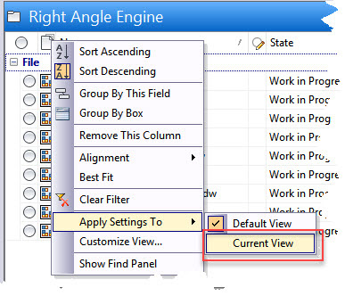
Next, create a filter to show only IDW files in the current folder using one of the methods shown earlier.  Next right click on the Entity Type column header and select "Apply Setting To Current View" from the context menu.


This will assign the filter to the IDW Files Only view saving it for future use in other folders. One thing to keep in mind, these views are only active in the folders they were selecting in.  If you select a different folder, the view will return to Default View.  While in the new folder selecting the view IDW Files Only will assign that view to the current folder until you change the view again even if the application is closed and then restarted.

Creating the filters and views you need for effective use of the Vault Client is an easy way to only display the files you need for certain tasks.  I will leave you with the reminder that filters can be applied to ANY column including custom columns created from your custom Vault properties.


Sunday, July 16, 2017

Changing the Default Workspace in Autodesk Vault Autoloader

Along with the installation of the Autodesk Vault Client all versions will also install the Autodesk Autoloader <version> for <Vault type>.  After installing the Autodesk Vault Professional Client 2018, you will find the Autodesk Autoloader 2018 for Vault Professional under the Data Management programs folder.  The main purpose of the Autoloader application is to provide a method of adding files to the Vault by folder(s) as well as creating visualization files, if desired, for all applicable files.

This article will not cover the use of Autoloader but will explain how to configure the default Vault workspace and library folder used by the application.  By default the Vault workspace folder must be named "Designs" and the library folder must be "Libraries"  in order to use the Autoloader.  Theses names may not be acceptable to your company.  In this example I have named my Vault workspace folder "Projects" and I used the default library folder name of "Libraries".

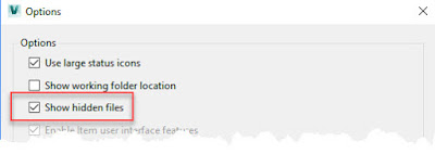
The first step is to configure the Vault Client to "Show hidden files".   Select "Tools" from the menu bar and then "Options" from the drop down list.

In the Options dialog box, place a check box is the box before "Show hidden files".  Select "OK" at the bottom of the dialog box to finish.

If you have not run the Autodesk Autoloader since you created the company Vault database you will not see the necessary configuration file.  Navigate in your Windows program directory and run the Autodesk Autoloader <version> for <Vault type>.  You will run the application  and allow it to create the default configuration file in the Project Explorer ($) folder.  On the first screen simply select "Next" to move to the Select Data Source dialog box.  Use the "Select Folder" icon to browse to the folder containing the CAD files you want to add to the Vault.   It is not import which folder you select but make sure the folder contains some CAD files.  In my case my folder contains a small Inventor assembly, parts and 2D drawings.   Select "OK" to continue.


You will immediately will be placed into the "Select Project" dialog box.  Here you will
"Browse" and select the Inventor project file which will resolve all the files in the folder selected above.  This is a topic in itself and I will not cover the ins and outs of which Inventor project file to use in this article.  Double left clicking on the project file will place a check mark beside it.  Select "OK" to continue.


You will now see a listing of the files, and folders if they exist, under the folder you select earlier.  You can remove any files or folders you desire because you actually only need one file to continue with the process.  Select "Next" to continue.


In the Data Scan & Report dialog box, select "Scan" to start the file validation process.  Once the process in complete you will receive an alert saying the process in complete.  At this point the "Errors in validation" count must be "0" or the "Next" button will not be available.  If there is an error in validation the dialog box will inform you of the problem beside each file in the "Status" column.  I will assume you can select "OK" to close the completion dialog box  and then the "Next" icon to move on.


The next dialog box is the familiar Vault log-in dialog box.  You must have administrator privileges to log in when using the Autoloader.  Once you enter your credentials, select "OK" to continue.


In the Map Vault Folders dialog box, I am going to select the "Target Location ..." to select the location for the placement of the DP Unit files.  In the resulting dialog box Mapping for "DP Unit", you will notice I do not have a choice of selecting my "Projects" workspace only the default "Designs" which is default.  Select "Cancel" in the Mapping for "DP Unit" dialog box to close it.


I will do the same thing for the Standard Parts "Target Location...".  This time the availability of the "Libraries" folder is present so the default location suits my purpose. 


 I must stop the process and correct the target location for the non-library files.  Select "Cancel" on the Mapping for "Standard Parts" dialog box to close it and then select "Cancel" on the Map Vault Folders dialog box to end the Autoloader process.  Acknowledge the message you wish to quit the application.

Move back to the Vault Client and select "Refresh" from the menu bar or press "F5" on the keyboard.  You will notice a configuration file called "BUU.xml" shows up in the Project Explorer ($) folder which was created by the Autoloader process I just finished.  You will also notice a new "Designs.ipj" Inventor project file which was created by the Autoloader.  We will remove this is a minute.

The next thing is the right click on the "BUU.xml" file and select "Check Out" to get a copy to your local Vault workspace and to make it available to modify.  Next right click on it again and select "Go to Working Folder".  This will place you in your local workspace ready to edit the .xml file.


Using the Windows Notepad application, open the "BUU.xml" file.   There are only two lines that you may need to modify, in my case only one since the "Libraries" entry is correct.  For my situation all I will change is the word "Designs" to "Projects" to match my Vault workspace folder name.  Once this is done, save and close the text file.

Back in the Vault Client, right click on the "BUU.xml" file and select "Check in.." from the context menu.  There is really no need to add a comment to the Check in dialog box since the file is normally hidden.  Select "OK" to finish the check in process.

Next right click on the "Designs.ipj" file and delete it from the Vault.  Next select "Tools" from the Vault Client menu and then "Options" from the drop down menu.  Deselect the "Show hidden files" then "OK' to close the Options dialog box.  


I need to delete the "Designs" folder from the Vault which was created by the Autoloader default configuration process earlier in the process.


I am finished with the configuration change.  The next time I use the Autoloader the "Projects" folder will be available for mapping the non-library files.


It is a long process but you only have to do it once for each company Vault which is normally only one.

Thursday, July 13, 2017

Using Inventor "Notes" as a Mini Vault

Inventor "Create Notes" function probably does not get a lot of use but for those who unfortunately do not have access to the Autodesk Vault, this feature can be turned into a mini Vault.  In this article I will outline the process of saving model versions, with images, using the "Create Note" command.  I know you can do this if you configure your Inventor project file to keep an unlimited numbers of "Old Versions" but that is across all Inventor files and can get cumbersome.

I will be using a part model but the process will work with assemblies as well.  I would not recommend it though because tracking the necessary part versions will be problematic.  You need to install the Autodesk Vault to handle assemblies effectively.  My part is a mounting post for a gearbox with a file name of 563549.ipt which will become important later in the article.  I am showing the browser so you can see the feature callouts.


An edit of the part is required, starting the process of capturing a version using the Inventor "Create Note" function.  Right click on the part name at the top of the browser and select "Create Note" from the context menu.


The first thing to do, after the Inventor notebook opens, is to remember to "Freeze" the thumbnail image so you will have a visual record of the current version.  Right click over the image and select "Freeze" from the context menu.  This prevents the image from updating as changes are made to the model later on.


Next, lazy left click the note name in the notebook browser.  Give it a descriptive name to help you remember this version.  Since this is my original, that will be my name.  You can also add dialog to the note box as well if desired.  


The next step is the main step in the process.  You will be using the "Insert Object" command to place a copy of the current Inventor part into the note area.  Select the "Insert Object" command in the Insert panel.


In the Insert Object dialog box, select the "Create from File" radio button, select "Browse" and navigate to the current part file, in my case it is 563549.ipt.  Place a check file in the "Display As Icon" box and then select "OK" to finish.  


The file will be added to the current "Comment" dialog box.  You may have to rearrange the box if needed.  You have finished capturing the current version, select the "Finish Notebook" command on the Exit panel.


The next thing is to save your part file then you can start making your version edits.  I am going to speed up the process and make two more version notes using the same process outlined above.   One important thing to remember is to make sure you save the part before using the "Insert Object" tool during the creation of any further version creations.  This will make sure the file will be representative of the desired version if it is ever restored.  Below are the image files from each version to make sure you understand my changes.


Time passes and I need to capture the design of the second version "Remove bar holes and Wrench Flats".  The first step is to open up the current file containing the three versions.  Next you need to use the "Save As" command to save the part file under a different name.  The name and file location is not important but the current file cannot have the same name as the file you will be restoring.  For my example I will choose 563549-1.


While in the newly renamed part file, highlight the note created from the version you would like to restore, right click and select "Display Note" from the context menu. 


Select the inserted object file then right click and select "Copy" from the context menu.


Exit the Engineer's Notebook and browse to the folder you would like to "Paste" the part version.  I am going to place it in the original folder, replacing the original file when prompted.  Returning to Inventor open up the part file to show you have restored one of the previous versions.  You could go back at anytime and restore an other version if needed. 

This process can be used to attach a different reference files or documents if needed.  Capturing an image will have to be done with an a screen capture application and pasted into the Engineer's Notebook if you desire an image.