Sunday, October 16, 2016

Edit Inventor Sketch Coordinates

When you have an Inventor part sketch that has a dimension being referenced from a point that is not along the axis of the sketch, you will probably have to add a construction line to get the location dimension you desire.  In the example below the 120 mm dimension would be impossible if you did not add the construction line from the corner first.


There is a better way to handle this sketch.  You can move and rotate the sketch X,Y coordinate system, for this one sketch, to allow the placement of the required dimensions.  Below is the same sketch with the sketch coordinate system rotated to match the angled edge.  The same dimensions can be placed without the construction line.


One of the best features about using this method is that the sketch coordinate system is remembered for only the current sketch and will revert back to the part original sketch layout coordinates for any future sketches.  Since it is remembered, if you come back to this sketch, the sketch coordinate system is restored for any required editing.  I would like to step you through the process of establishing a new sketch coordinate system.  I will use the same model.  I will start by a new sketch on the face.  You will notice the original part orientation will place the sketch coordinates to match.

You will find the "Edit Coordinate System" tool under the Sketch tab on the Constrain panel in the drop down panel.


Inventor will prompt you to left click to select the existing origin.  Pick the small blue ball at the center of the existing sketch coordinate system.  The coordinate system will then be attached to your cursor so you can move it anywhere you desire.  Please note it will not actually physically float around but the "+" symbol beside your cursor arrow indicates that it is attached.


Next left click to select the point you want to be the new sketch origin.  I will be using the lower corner of the the angle cut for my example.  The sketch coordinate indicator will jump to the new location.


The next step is to align the desired sketch axis with the edge.  I will be using the X-axis.  Left click on top of the X-axis rod, not the arrowhead.  It will highlight as you pass over it to make sure you are ready to select it.


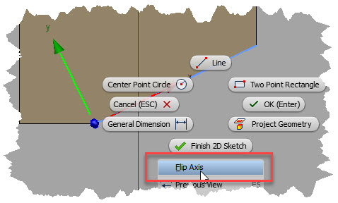
Next you want to left click to select the edge of the model you want to align the selected axis.  In my example I will select the angled model edge.  The sketch coordinate icon will align with the selected edge.  If it is flipped the wrong way simply right click and pick the "Flip Axis" command for the context menu.


The last step is to right click and select "OK" for the context menu or simple press the "Enter" key on the keyboard.  You will see the origin, X and Y axis shift to the new location.  The orientation of the sketch to the screen may be disturbing, but we will take care of that next.


The easiest way to re-orient the sketch so the sketch coordinate system is square to the screen is to select the "Look At" command located on the Navigation Panel and then pick the active sketch in the Inventor Browser.

Finish your sketch as you would normally do.  The next sketch you add to the part will follow the original sketch coordinate system.  If you edit this sketch, the modified sketch coordinate system will be restored.

You have to admit this is a very cool function to add your sketching ability and speed.

Wednesday, October 5, 2016

Let's Take a Look

In our digital age, we are often faced with having to find a viewer for an engineering file we have just received from another engineer, supplier or client.  In most cases we only need to view the file in order to see what a supplier is furnishing as the result of an order, comment on how a supplier has developed a component or any number of other reasons.  Most firms will only be using one or two different CAD applications and these are often not the ones other firms are using for component development.  Sure we can ask them to supply a native CAD version but sometimes users may not have any CAD applications installed to view it with.  Whatever the reason, we need a universal viewer that will get the job done quickly and give us insight on how a project is developing.

Autodesk is supplying such a free web based tool to the public.  It is called the Autodesk A360 Viewer and can be found at this address.   Autodesks only requirement to use this viewer is an Autodesk User ID which is also free which will unlock a few other free utilities as well.   If you do not have an Autodesk ID, you can sign up right here using your email address.


Once on the site, after you have signed,  you may want to see a list of all the design application file types it supports.  Click on the "2D and 3D formats supported" hyperlink to display the list, it is truly incredible!


 The next thing is to select the "Upload your design" icon and browse on your local workstation for the file you desire to view.  The application is pretty intelligent and will quiz you if it thinks that the file you have chosen requires other files to be uploaded as well to support it.  For example if you select an Inventor assembly (IAM) file, it requests the supporting part files (IPT)  to be uploaded as well.


 If you select an AutoCAD file, it will prompt you for any supporting files such as Xreference files.  If there are none, simply chose "No more files" to continue.

Once the upload starts, the viewer will begin to develop the 2D or 2D view.  If you do not want to wait, it tells you it will email you when it is finished and will give you a link to open your file view.


There is a note in the email that is important to read.  The Autodesk A360 Viewer requires a web browser that supports WebGL 3D graphics so Microsoft Internet Explorer is not a good choice.  I have used both Chrome and Firefox with great success.  The email will also give you a web address which you can send to others to view the file.  This ability can be also found on the A360 Viewer tools.

Once you are viewing the file, you will have a variety of tools to manipulate the model.  These are located at the bottom of the viewing screen.  They vary depending on the type of file, the 3D and 2D tool bars are shown below.


 Up at the top right of the viewing window are some standard tools for adding comments, getting a web link to the design to share with others, printing and taking a screenshot.  The most valuable one is to "Save to A360" if you are using this collaboration tool.

 
 One of the most interesting tools, found on both tool bars is the "Live Review" option.  When multiple reviewers are online, the live review can be executed.  It is only a textual exchange but it can be valuable to viewing group discussi0n.

One last thing I want to point out is that all designs placed on your Autodesk A360 Viewer page will be deleted after 30 days.  If you require a longer period you have the ability to request it by selecting the "Extend" icon located on the Recent Uploads page.  You can delete any old files by clicking on the three dots indicated below to display the "Delete" command.

 I cannot tell you how many times in the past I wish I had access to this viewer service especially one with so many tools and options.  Be sure to upload a file or two and take a look for yourself, you will be glad you did.