Showing posts with label iFeature. Show all posts

Sunday, August 28, 2016

Creating an Inventor iFeature - Part 2

I will continue with the creation of an Inventor iFeature by covering how to edit existing iFeature, how to add user instructions, which can be displayed during placement, and how to create a table driven iFeature.  If you have not previewed the first article, on the creation of an iFeature, you can find it here.

I will continue with the iFeature from the first article which creates an internal bore with keyway by entering the desired bore and keyway width.
You can open an iFeature inside Inventor for editing.  The file extension is .IDE and normally is in the folder designated in your Inventor Application Options.  Once opened you will have three main icons across the main panel.  We will use the "Edit iFeature" command first.  

After selecting the command you will be presented with the Edit iFeature dialog box which looks very similar to the one used to create it.  You will notice that you are restricted in the things you can edit.  Feature geometry cannot be added or deleted from the iFeature which is why I mentioned in the first article to save your original model so if you have to change the iFeature geometry, you erase the old one and create the iFeature from scratch.  If you need to change the name of the iFeature, prompts, limit designation and default values, all can be accomplished here.  After making any changes select "Apply" to finish then save the iFeature.

Before I close the iFeature, I would like to add a Microsoft Word help file so users may open it during iFeature placement if they are unfamiliar with the required picks and clicks.  Click on the Tools tab then the "Import Object" command on the Insert panel.


In the Insert Object dialog box I will select the "Create from file" option then "Browse" to a previous created Microsoft Word document.  Select "OK" to finish.


This will place the document as a 3rd Party attachment in the Inventor Browser.  One last step is required to designate it as the help file for the iFeature.  Expand the entry and then right click on the "Embedding 1" entry.  Select "Placement Help" for the context menu to place a check mark beside it.  Save the iFeature file when finished.


The next time you place the iFeature in a model, you can activate the help file by selecting the icon shown below.  The help document will be open in a new window using Microsoft Word.  Of course you must have Microsoft Word installed on your computer if you use this process.  Other types of documents my be used PDF, Web Pages or text files.


I saved the best for last.  This iFeature is a great candidate for making it table driven.  All internal bores have standard width keyways.  The current iFeature requires you to enter the correct keyway width for the desired bore.  You may know them by heart or you may have to look them up each time you use the iFeature.  The internal bore diameter and the keyway width can be added to a table from which you can then simply select the desired bore and the iFeature will select the matching keyway width during the iFeature placement.  Open up the iFeature again and select the "iFeature Author Table"command.  This will open up the iFeature Author dialog box.


You will notice all of the model named parameters have been automatically added to the table.  I am only concerned with the "Bore" and the "Keyway_Width" columns.  Right click on the first entry and select "Insert Row".  Edit the column entering the next standard bore and matching keyway width.  You can repeat this process for as many standard bore diameters as your company needs.


You can always edit the iFeature at anytime to add or remove bore and keyway entries.  The next step is to assign as many column keys to the table as desired.  Designated key columns are the only ones displayed during iFeature placement.  I will  specify the "Bore" column as my first and only key column.  Right click on the column title and chose the key number desired.  Select "OK" to close the dialog box and save your iFeature.  One thing you need to notice is once the iFeature becomes table driven the "Edit iFeature" icon is not available.  All available changes will be made from the iFeature Author Table command.  Also the "Edit using Spread Sheet" command becomes available which allows the editing of the iFeature table using Microsoft Excel if you have it available.


The next time you place the iFeature in your model you will only see the "Bore" listing which you can select from and it will automatically apply the correct keyway width to the model.  The bore listing is also available if the iFeature needs to be edited to a different bore value.


As you can see Inventor iFeatures are a valuable asset to your design process both for speed of placement but accuracy making sure the proper keyway is always used.

Friday, August 26, 2016

Creating an Inventor iFeature

When designing in Inventor there will be part features that you will reproduce over and over.  These include features such as wrench flats, internal and external keyways, setscrew flats and many more.  iFeatures in Autodesk Inventor make placing these repetitive features easy and extremely quick.  Not only can they be used to add features to an existing part but they can be used to create the part from scratch.

I would like to use this article to explain the process of creating an iFeature for placing an internal bore with a keyway as shown in the model below.


The first step is to create the model with the features you will be capturing in your iFeature.  I have a few suggestions that I find helpful when creating the model.  These are:


  • Keep the sketch as simple as possible.
  • Avoid reference geometry
  • Add descriptive names to your parameters as you create the model.  These will automatically populate into the iFeature.
  • As in all good Inventor modeling, keep you sketch related to the origin of the part.  In this model the bore sketch is centered on the origin of the part.
  • Keep your sketch constraints to a minimum.  The only one I normally use is the coincident constrain to tie the sketch center to the center of the origin.  Use parameter dimensions instead.
My sketch for this iFeature is shown below.  I have turned on dimensional expressions to show the parameters used in the iFeature.  The parameter table is also show which has been filtered to only show key parameters.


 The keyway broach depth is calculated by determining the length of the right triangle leg, indicated by the red arrow, and then adding half of the standard square key plus the radius of the bore.  Inventor has a great calculator and a versatile set of mathematical operations and functions built right into the software.  If you are not familiar with these, take a look at this Autodesk Knowledge Network article.  The parameter Keyway_ Depth equation is explained below.


Once you have completed your sketch, extrude the bore and internal keyway as a single feature using the "All" extents option.  This will make sure the iFeature will create a bore and keyway completely through any thickness part.

Before you create your iFeature make sure you save your master part.  This is not required by Inventor but if you need to edit the iFeature geometry it is a lot easier to recreate the iFeature from a modified model than editing the iFeature geometry itself.

When you are ready select the "Extract iFeature" command located under the Manage tab in the Author panel.


In the Extract iFeature dialog box the first thing you want to do is name the iFeature.  Spaces are not allowed.


The next step is to select the model feature(s) you want to include in the iFeature.  Looking at the browser, left click on "Extrusion 2" which will add it into the iFeature dialog box.  Do not select extrusion 1 because we are not interested in the addition of the base feature although this could be a possible option.


Take note that the iFeature prompts will automatically be configured using the model parameter names.  You can change them if you desire and in my case I will rename some that will automatically be calculated to help the user avoid them.  You may also wish to rearrange them by using a left click and drag routine.  We will not be using the "Limit" column in this iFeature but please explore the possibilities it offers.


The last area of the dialog box is the Position Geometry where there is only one entry at this point.  Think about what geometric features you will need to select in your model to place this iFeature correctly.  You will need to specify the profile plane or model surface to begin the bore and keyway, this has been already added.  You will also need to select the center of the model to place the bore and keyway, this one must be added.  To accomplish this highlight the Reference Point 1 in the Selected Features tree and use the indicated icon to add it to the Position Geometry box.


The order of the Position Geometry box can be altered as desired using a left click and drag method.  You may wish to edit the Prompts to more clearly describe what the user must select when placing the iFeature.  I my case I have done this.


You are finished with the iFeature creation and you need to save it.  If you select the "Save" icon, Inventor will automatically direct you to the location defined in the "Application Options".  You can use this or place it to a folder of your choice.  I would suggest selecting a folder within your project file scope to avoid problems down the road.  If you named the iFeature the save routine will automatically use this name.  Below is a screen shot of the Application Options showing the iFeature tab.


The last thing is to take you new iFeature for a test drive.  Open up or create a new part and then select the "Insert iFeature" command which is located on the Manage tab on the Insert panel.


Select the iFeature for the catalog dialog box which will then bring up the Insert iFeature dialog box.  The first Geometric Position prompt is automatically highlighted and the custom prompt I entered is visible.  After selecting the two Geometric Positioning requirements select "Next" to continue.  


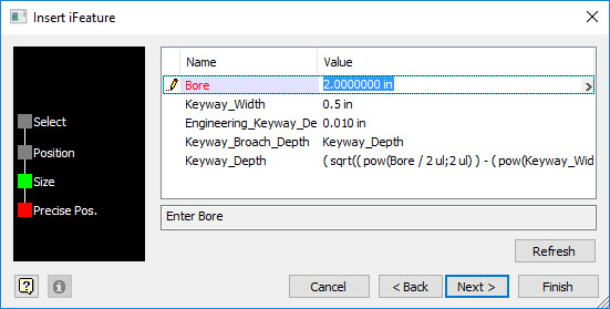
Fill in the bore and matching keyway width and modify the standard engineering clearance amount if required.  This iFeature does not require any supplemental sketch modification so select "Finish" to place the iFeature.  


If you should need to change the placed iFeature bore and keyway width, right click on the iFeature in the browser and "Edit iFeature" from the context menu.  This will display the iFeature parameters dialog where you can make required size changes.


At this point you should be patting yourself on the back and also realizing the potential benefits of using iFeatures.  In  the next article I will will address editing and creating a table driven iFeature.  We will use the same one you just created and alter it so you can select the desired bore and matching keyway width from a drop down list.