Showing posts with label parameters. Show all posts

Sunday, November 25, 2018

Modifying Plastic Bottle to Hold Exact Measure

I had a problem presented to me to determine the volume of liquid an existing bottle held and then modify the bottle, using Fusion 360, so it would hold an exact US Imperial Quart of liquid.  The plastic bottle model given to me to start with was a dumb solid body, no features or parameters.  I decided to use Fusion 360 to determine the existing volume the bottle would currently hold but to also use it to modify the bottle to hold the required volume.


In my video I used a variety of processes in Fusion 360 including:
  • Parameters
  • Solids manipulation using Combine, Split Body, Body Remove and others
  • Workplane creation
  • Move/Copy command
  • and others  
Please take a look and see how Fusion 360 can make the re-design of a product easy.

Monday, November 13, 2017

Autodesk Fusion 360 Parameters

Autodesk Fusion 360 adds a parameter to every dimension you add to your model whether you realize it or not.  These parameter are create consecutively starting with d1, d2, d3, etc.  Existing parameters can be reused in other dimension to add "parametric' features that can aid in controlling the model design.  For example, I have sketched a rectangular box with a length of 8 inches and a width of 6 inches.  I rename the parameters from d1 and d2 to Length and Width.  I then place another rectangle on top of the first which I want to be always half of the size of the first.  Using the existing parameters I simply add dimensions to the length as Length/2 and  width as Width/2 to accomplish this.  Every time I modify the first rectangle's length and width the second one will resize also.

Take a look at my YouTube video and you will see some of the possibilities you have with using parameters in Fusion 360.


Thursday, July 6, 2017

Using Inventor Sketch Blocks for Feature Placement

When we uses AutoCAD for our 2D designs, we often turned to the Block and sometimes the Group feature to combine numerous entities together in order to select and perform operations on all the entities at once.  We could not live without them.  Along came Dynamic Blocks and we found even more uses for them.

A lot of designing has moved into the 3D world as we moved from AutoCAD to Inventor but our love for blocks did not follow along.  Inventor has the ability to create and save Sketch Blocks inside IPT files.  These blocks can be simple or can be complex parameter sketches that group sketch entities together making repetitive sketches easier and definitely faster.  In this article I want to demonstrate one use of a parametric sketch block to place an external shaft keyway.  

One of the first things to consider is where you would like to develop the sketch block.  This block will be used for the design of numerous shafts so you may want to place it in your IPT template.  Some designers use a master sketch block part where all the special sketch blocks are saved and can be copied to any new part when needed.  We will get into the methods of doing this later.  I will be choosing the second method.

The first step is to create a master sketch and add dimensional parameters to it. I also changed the color property of the sketch entities.  This will serve two purposes, it will denote that this is a sketch block and the color change will be dramatic when it is placed and full constrained.  The original parameter values are not important, these are for a 2 1/2 inch shaft.


The next step is to create the sketch block.  While still in the original sketch, select the "Create Block" command.  You will find it under the Sketch tab in the Create drop down menu in Inventor 2018.


The "Select" icon will already be highlighted in the Create Block dialog box.  Using a window or crossing select all the entities from your sketch which will be a part of the sketch block.  Do not worry about the parametric dimensions, they will be included automatically.  Once you are finished selecting your sketch, pick the "Select" icon under Insert Point and I suggest also placing a check mark in the "Visibility" box.  This will show a small red "+" on the block indicating the insertion point when you later place the block.  This of course is not required.  Give the block a distinctive name since you may have other sketch blocks in your model, a description is optional.  Select the "Insert Point" in your sketch and then select "OK" to finish and create your sketch block.


If you make an error, you can select the newly created block and right click to bring up "Edit Block" in the context menu.  This command is available if you are in the original sketch or not.  One note of caution here, you cannot edit the insert point using this routine.  If you selected a bad insertion point, delete the sketch block from the Browser folder and recreate it.


Once you are satisfied with the sketch block you should delete the original development sketch from the model.  Last you need to save the IPT or IPT template to make the sketch block a permanent part of the IPT.

Now you should try out your creation.  If the sketch block was created in your IPT template, create a new drawing, if it was a part of a standard block IPT, as mine was, use the "Save As" command to create a new IPT.  Either method will create a new part model with the included sketch block and the parametric values.  I will talk about other ways to create a new files later on in this article.  

In your new model create your shaft.  If you use the "Cylinder" primitive function this step will take you only a few seconds.  For my demo shaft I will create a 3" Diameter shaft, 10 inches long.  At this point do not add any end chamfers, it will only complicate the placement of the sketch block.  Next you will create a workplane tangent to the outside surface of the shaft parallel to one of the origin planes running the length of the shaft.  At this point the model looks like this.


Next create a sketch on the workplane you just created.  You are ready to place the External Keyway sketch block.  This can be done using one of two methods, either left click and drag the sketch block from the Browser folder or right click on the sketch block and select "Place Block" from the context menu.  One the sketch block in on your cursor select the insertion point in your sketch, probably somewhere along the axis of the shaft although this is not necessary since you will be applying sketch constraints to accurately position it is a moment.


This is a completely new sketch so you will need to add sketch constrains to position the sketch block.  In my sketch block the points outside of the slot sketch will be constrained to one end of the shaft with a coincident constrain.  If you refer back to the original sketch, this point is used to locate the slot along the shaft length.  Once the sketch block is constrained it will change color, this is one reason I like to make my sketch blocks red, the change is dramatic.  


The next step is to "Extrude" it as a cut by listing the model parameters, selecting "Width_of_Keyway" then adding "/2" since all inch keyways are cut so half their width is inside the outside tangent of the shaft.


The last step is to open the Parameter table and edit the values of the sketch block to match the current shaft size.  

You can streamline the previous step by creating an iLogic table to help you fill out the parameters. 


The shaft keyway is finished!  Add a couple of chamfers to each end of the shaft and you are done.  I encourage you to do another one for practice and see just how fast you can place external keyways.

I mentioned earlier that I would cover other ways of distributing your sketch blocks.  If you have an existing part model and would like to add your configured sketch blocks to it just use the "Derive" command and select the sketch blocks you would like to include.  If your sketch blocks include parameters, do not forget to include them in your selection.


I would suggest that you "Break Link With Base Component" once you have derived all the features into your part model and even go one step further and delete the derived component from the model to avoid confusion.

The last method of copying sketch blocks and their supporting parameter values is to use the "iLogic Design Copy" command located on the iLogic panel under the Tools tab.  This is only available if you do not have any models open in Inventor.


Sketch blocks can be copied directly from model to model by right clicking on a sketch block(s) and selecting "Copy" from the context menu.  Moving to you new model, right click on top of the Browser and select "Paste".  One disadvantage to this method occurs if the sketch block has any attached named parameters.  The parameters are copied but the configured parameter names are lost.

This is just one use of sketch blocks.  You could not live without AutoCAD blocks, I think you will find Inventor sketch blocks just as valuable.

Friday, August 26, 2016

Creating an Inventor iFeature

When designing in Inventor there will be part features that you will reproduce over and over.  These include features such as wrench flats, internal and external keyways, setscrew flats and many more.  iFeatures in Autodesk Inventor make placing these repetitive features easy and extremely quick.  Not only can they be used to add features to an existing part but they can be used to create the part from scratch.

I would like to use this article to explain the process of creating an iFeature for placing an internal bore with a keyway as shown in the model below.


The first step is to create the model with the features you will be capturing in your iFeature.  I have a few suggestions that I find helpful when creating the model.  These are:


  • Keep the sketch as simple as possible.
  • Avoid reference geometry
  • Add descriptive names to your parameters as you create the model.  These will automatically populate into the iFeature.
  • As in all good Inventor modeling, keep you sketch related to the origin of the part.  In this model the bore sketch is centered on the origin of the part.
  • Keep your sketch constraints to a minimum.  The only one I normally use is the coincident constrain to tie the sketch center to the center of the origin.  Use parameter dimensions instead.
My sketch for this iFeature is shown below.  I have turned on dimensional expressions to show the parameters used in the iFeature.  The parameter table is also show which has been filtered to only show key parameters.


 The keyway broach depth is calculated by determining the length of the right triangle leg, indicated by the red arrow, and then adding half of the standard square key plus the radius of the bore.  Inventor has a great calculator and a versatile set of mathematical operations and functions built right into the software.  If you are not familiar with these, take a look at this Autodesk Knowledge Network article.  The parameter Keyway_ Depth equation is explained below.


Once you have completed your sketch, extrude the bore and internal keyway as a single feature using the "All" extents option.  This will make sure the iFeature will create a bore and keyway completely through any thickness part.

Before you create your iFeature make sure you save your master part.  This is not required by Inventor but if you need to edit the iFeature geometry it is a lot easier to recreate the iFeature from a modified model than editing the iFeature geometry itself.

When you are ready select the "Extract iFeature" command located under the Manage tab in the Author panel.


In the Extract iFeature dialog box the first thing you want to do is name the iFeature.  Spaces are not allowed.


The next step is to select the model feature(s) you want to include in the iFeature.  Looking at the browser, left click on "Extrusion 2" which will add it into the iFeature dialog box.  Do not select extrusion 1 because we are not interested in the addition of the base feature although this could be a possible option.


Take note that the iFeature prompts will automatically be configured using the model parameter names.  You can change them if you desire and in my case I will rename some that will automatically be calculated to help the user avoid them.  You may also wish to rearrange them by using a left click and drag routine.  We will not be using the "Limit" column in this iFeature but please explore the possibilities it offers.


The last area of the dialog box is the Position Geometry where there is only one entry at this point.  Think about what geometric features you will need to select in your model to place this iFeature correctly.  You will need to specify the profile plane or model surface to begin the bore and keyway, this has been already added.  You will also need to select the center of the model to place the bore and keyway, this one must be added.  To accomplish this highlight the Reference Point 1 in the Selected Features tree and use the indicated icon to add it to the Position Geometry box.


The order of the Position Geometry box can be altered as desired using a left click and drag method.  You may wish to edit the Prompts to more clearly describe what the user must select when placing the iFeature.  I my case I have done this.


You are finished with the iFeature creation and you need to save it.  If you select the "Save" icon, Inventor will automatically direct you to the location defined in the "Application Options".  You can use this or place it to a folder of your choice.  I would suggest selecting a folder within your project file scope to avoid problems down the road.  If you named the iFeature the save routine will automatically use this name.  Below is a screen shot of the Application Options showing the iFeature tab.


The last thing is to take you new iFeature for a test drive.  Open up or create a new part and then select the "Insert iFeature" command which is located on the Manage tab on the Insert panel.


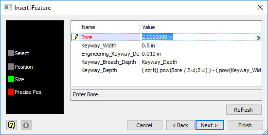
Select the iFeature for the catalog dialog box which will then bring up the Insert iFeature dialog box.  The first Geometric Position prompt is automatically highlighted and the custom prompt I entered is visible.  After selecting the two Geometric Positioning requirements select "Next" to continue.  


Fill in the bore and matching keyway width and modify the standard engineering clearance amount if required.  This iFeature does not require any supplemental sketch modification so select "Finish" to place the iFeature.  


If you should need to change the placed iFeature bore and keyway width, right click on the iFeature in the browser and "Edit iFeature" from the context menu.  This will display the iFeature parameters dialog where you can make required size changes.


At this point you should be patting yourself on the back and also realizing the potential benefits of using iFeatures.  In  the next article I will will address editing and creating a table driven iFeature.  We will use the same one you just created and alter it so you can select the desired bore and matching keyway width from a drop down list.

Tuesday, August 16, 2016

Methods of Sharing Parameters Between Inventor Parts - Part 3

In this article I will cover the last two methods of sharing parameters between Inventor parts.  If you have not preview the first two articles, the first one can be found here and the second one here.  The third method is to "Export Parameters".  I will be using the same model as before with two model parameters and one user parameter.


In the original model you can export parameters to an .XML file which you can later import into another part model.  These two commands are found under the Manage tab in the download menu on the Parameters panel.


Selecting the "Export to XML" command will allow you to save the current part parameters to a file of your choice.  After saving, you can use the "Import from XML" command to a the exported parameters to a new part or an existing file.  The imported parameters will be added to the part as User Parameters.  Make sure you are aware that this includes all parameters from the part that the export XML command was executed.  This is not normally a problem because of the "Purge Unused" command inside the Parameters dialog box.  Once you have used the parameters which were imported, this command will allow you to purge all unused parameters from the part.


Please note that this process removes all Key and Export Parameter check marks from the original exported parameter table.

The last method is "Save As".  This may seem an obvious and useless method but can be quite valuable if you are creating multiple similar parts. The parameters from the original part are copied across into the new part created using the "Save As" or "Save Copy As" commands.  One advantage of using this method is the existing Key and Export Parameter are preserved.   If you remove a part feature, the model parameters, for that feature or sketch,  are removed but user parameters are maintained.

So there you have a variety of methods to share parameters between Inventor part files.  Each one has pros and cons and serve various purposes.  I suggest that you practice with all of these and find the best situations for each.  Also try using them between assembly files.  You will have success with all except the "Derive Part" command which is to be expected from the command name.

Tuesday, August 9, 2016

Methods of Sharing Parameters Between Inventor Parts - Part 2

In this article I would like to continue with the methods of sharing parameters between Inventor parts.  If you missed the first article, I suggest you click here to review it before continuing.  The second method of sharing parameters is linking parameters between parts.  The process begins inside the Inventor Parameters table which can be opened from the Quick Access Toolbar, if it is enabled, or from the Manage tab on the Parameters panel.

I am using the same part model from the first article which contains two model parameters and one user parameter.


I will next create a new part and open up the Parameters table.  At this point it is empty because I do not have an saved parameters in my Inventor part template.  I will click the "Link" icon at the lower left of the table.  At the bottom of the resulting Open dialog box I have selected "Inventor Files" as my file type and selected the Hole Plate,ipt as my source file.  Select "Open" to continue.


The Link Parameters dialog box opens and you have to opportunity to select which model parameters you wish to link with the new part.  The small green arrow means these parameters have been exported from the referenced model.  Select the gray ball beside each parameter to enable linking and select again to return to a non-linked state.  I have selected all three parameters.  If you remove the check mark beside"Show All Parameters" only the exported parameters will be available for selection.  Select "OK" to continue.


The selected parameters will appear under User Parameters in the Parameters table listed under the path of the file they are referenced from.  They cannot be edited in this state which is indicated by the gray background and will automatically update if the source file parameters change.


Starting a new sketch, you may wonder how to use the parameters directly in the sketch dimensions.  The familiar ">" symbol on the right hand side of the dimension box is not available which would allow you to select model parameters from a list.  A little trick to make the selection symbol appear is to type the "=" key, then you can select parameters from the drop down list.


After you have used the linked parameters, they will appear under the Model Parameters in the Parameters table.  


The Lgth and Width parameters are still linked to the Hole Plate.ipt and will update automatically if the parameters change in the referenced model.  There will be times when you desire to break the link between the new part and the referenced file.  This is easily accomplished by two methods.  The first is to open up the Parameters table in the new part, right click on the linked file path and select "Delete Folder".  This will break the link for the Lgth and Width parameters turning them into editable User Parameters since they have been used.  The Hole_Dia parameter will be lost because it has not been used in the new part.


If you desire to break the parameter link for one or more parameters and retain the parameters that have not been used, right click on the reference file and select "Edit Folder".   In the Link Parameters dialog box you can deselect the parameters you which to break the link.


The resulting Parameter table is shown below.  The Lgth and Width parameters become User Parameters independent of the referenced part and the Hole_Dia remains linked and available for use in the new model.


In the next article I will cover the other two options for sharing Inventor part parameters.


Monday, August 1, 2016

Methods of Sharing Parameters Between Inventor Parts

There will be times when you have an Inventor part and would like to share or copy the parameters into another part for use in size or placement dimensions.  There are a variety of ways that Inventor can accomplish this all of which will transfer the parameters between parts but each method will treat the parameters differently.  I will describe these four methods and explain the resulting parameters.  These four methods are:

  1. Derive Part
  2. Link Parameters
  3. Export Parameters
  4. Save As
My model is a simple plate with four equal holes.  The Lgth and Width are "Model" parameters while the Hole_Dia is a "User" parameter.  The parameter table for the part is shown below.

Using the "Derive" command is probably the most used and versatile method of sharing parameters between parts.  When a new Inventor part is created, the "Derive" command is located  under the 3D Model tab in the Create panel.


I will not attempt to explain all the options available in this command but will concentrate on the deriving of parameters from one part to another.  In the Derive Part dialog box the parameters of the part being derived from are listed at the bottom of the tree.  You have the option to select which ones you wish to "derive" from the original part into the new part parameter table.  In this example I have selected the two model parameters and the one user parameter by selecting the circle beside each until it shows a "+".


By default these parameters are linked to the original file.  If these parameters are changed in the original file, the new part derived parameters will update to match.  This behavior can be suppressed or prevented by modifying the "derived" component settings in the browser.  Right click on the derived component and choose either "Suppress Link with Base Component" or "Break Link with Base Component".  It is important to remember the break link cannot be reversed once the part is saved.


All of the derived parameters are shown in the new part as User Parameters.  The gray background indicates that they are linked and the base component is listed at the top.  It is important to remember that additional parameters may be added to the derived part which are unique to the derived part and are not dependent on the base component.  These can be either model parameters, user parameters or both.

If the derived link to the base component is broken, the derived parameters are released and can be edited as needed within the new part.  Using this method you can create a similar but different parts easily.  


This article is getting a bit long so I will cover the other three methods in another article.