Showing posts with label Autodesk AutoCAD. Show all posts

Monday, September 5, 2016

I Installed the Vault Client, Where is My AutoCAD Vault Add-in Ribbon Tab?

You have installed the Autodesk Vault Client it seems without a hitch.  You open up AutoCAD and the Vault tab is missing.  You scratch your head and wonder what when wrong? 


Take heart, it usually is something very simple.  From this point on, you must be an Administrator of the workstation you are working on.  The first thing to check is if you configured the Vault Client installation to add the Vault Add-in for AutoCAD.  Make sure you close all running programs and go to the Windows Control Panel.  Select "Programs and Features" from the list.  Please note that I have configured my Control Panel for small icons which makes it easier to find.

After the installed Programs and Features have fully loaded, browse down to the Vault Client installation for your version.  In my case I have installed Autodesk Vault Professional 2017 (Client).


Right click on the entry and left click the "Uninstall/Change" option.  Don't worry, you have to choose another option later on if you are uninstalling the application.  Once the application installation routine has loaded, left click the "Add or Remove Features" icon.


The Vault Client feature list will appear.  Look at the list carefully, it represents all the applicable Autodesk applications installed on your workstation that can be configured with the Vault Client Add-in.  In my example, the "AutoCAD 2017 Add-in" is not checked which in turn did not install the necessary AutoCAD Vault Tab.  This could have occurred for two main reasons.  The Autodesk Vault Client was installed "before" the Autodesk AutoCAD application or someone unchecked it during installation.  Left click in the small box to place a check mark.  Select "Update" in the lower right hand corner of the dialog box to continue.  NOTE: If there already is a check mark, skip this step and select "Cancel" at the bottom right side of the dialog box and read on.


Occasionally you will be presented with the following dialog box which is requesting the location of the Vault installation files.  You may have to seek the help of your system administrator as to the files location and then simply use the "Browse" icon to locate it and then press "OK" to continue.


Once the screen informing you that the product was successfully upgraded, select the "Finish" icon to close the application.  Also close the Windows Control Panel.  Next run your AutoCAD application.  Sometimes the Vault Add-in will load up and the Vault tab will appear and you are finished.  If it still does not appear, you have one more step to execute.  Open a new drawing using any template your desire and type "CUILOAD" on the screen and then press "Enter".

This will bring up Load/Unload Customizations dialog box.  The listing at the top are the currently loaded AutoCAD user menus (called customizations).  You will notice that the "Vault" entry is missing.  Select the "Browse" icon at the bottom of the dialog box to continue.


Browse in the folder C:\Users\<current user>\AppData\Roaming\Autodesk\AutoCAD <version>\R<release>\enu\support (normally the default folder) and select the "VaAc.cuix" file.  Select "Open" to continue.


Back in the Load/Unload Customizations dialog box, select the "Load" icon to add it to the Loaded Customization Groups list.  Select "Close" to finish.


At this point, you should have a new "Vault" tab on your AutoCAD ribbon and you are ready to go.


Saturday, June 18, 2016

Using the AutoCAD "MVSETUP" Command

In an earlier post I covered how to configure the AutoCAD "MVSETUP" command by adding your companies title block(s) and matching viewport(s) area to the "mvsetup.dfs" file.  Please click here if you have not already read this article.  This article will continue with the some of the uses of the "MVSETUP" command.

A few things we need to mention before using the command.  The command has the ability to set the correct layer on which to place the drawing title block but it does not have the ability to change the paper space page setup.  My template default to an ANSI B-Size sheet so if I use the "MVSETUP" command, I either must use my B-Size title block or change the page setup before execution of the command.

The other drawback of the command is it does not have a built in routine for setting the layer for any inserted viewport(s).  I mentioned it can set the layer for placement of the title block but you would never want to place viewport(s) on the same layer.  With these conditions explained let's run through the use of the "MVSETUP" command.

I will start the command while I am in the model space environment.  The first question the command asks is if I would like to switch to paper space.  If I were already in paper space, this prompt will not appear.  I wish to work in paper space so I either tap enter, the spacebar or left click on "Yes" to continue.

 
From the list of command options I will use my mouse to select "Options".  My default template layer is "Object" but I would like to place my title block on the "Title_Block" layer.  Layer control is located under "Options".

 
The next command options have a few standard settings for a new drawing but most of these are automatically set by my template.  There may be an occasion I would need to change the units which I could do now as the command will return to this option panel when each option is finished.  I will choose the "Layer" option.
 
The routine will prompt me for the layer name, it does not offer a list to choose from.  If the layer has been previously set, you can simply press enter to continue to use the default layer.  In my case, I will type the layer name and press enter.  One of the nice things about this layer change is that it will place the title block on the chosen layer but will not change the drawing default layer.
Once the command returns to the previous option menu, I will simply tap the enter key to accept the "Exit" option to return to the previous dialog box.


The command presents the previous options and I will select "Title Block" because that will control some of the following operations.  If you remember, the "mvsetup.dfs" file contains my different title block drawings but also the definition for the available viewport(s) space.  Using my mouse I left click on "Title Block" to continue.

The next options panel default to "Insert" which should be ok to use since it automatically inserts you title block at 0,0 with a scale value of 1.0 and a rotation of 0 degrees.  If this is not OK you do have the option to change the location origin.  I simply press the enter key to continue.


The routine will now open the AutoCAD Text Window and present the list of available title blocks.  The four title blocks I added are at the bottom of the list.  Refer back to the previous post if you need to configure this file.  Type in the number of the desire title block.  In my example I will type in the number 14 and press enter.


At this point the configured title block drawing is placed on the paper space sheet.  One short coming of the command is that you do not have the ability to enter attribute information during the insertion process.  You will have to edit the title block attributes after the routine is finished.


I will continue with the command options and add a single paper space viewport to the drawing.  I select the "Create" option and the command presents the next option screen.  I will select "Create Viewports" from this list.

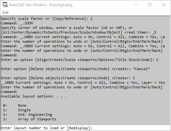
Another AutoCAD text window will open which will give your four options.  Type in your desired viewport configuration by number and press enter.  For multiple equal size viewports with configurable spacing use option 3, in my case I will type 1 since I only want a single viewport.


The routine will prompt you for the first point and second point if you desire to sketch your viewport.  If you desire to use the "default" viewport size from the "mvsetup.dfs" file, then chose "Default" and press enter.  The single viewport will appear to these coordinates define in the configuration file.


The next option I will choose is the "Scale viewports".  The command first prompts you to select the viewport object.  Press enter to continue.

The command will ask you to enter the number of paper space units with a default of <1.0>.  Normally you will hit enter at this prompt.  Next it will ask your for the number of model space units.  You will enter the number of model space units that will be represented by one paper space unit.  In my example I want my viewport to be set to a scale of 1:2 so I will enter 2 at this prompt and press enter to complete the viewport scaling.  It is important to remember that this command does not have the ability to "Lock" the viewport.


There are numerous options for the control of the viewport but for this article I will leave the "MVSETUP" command at this point by pressing ESC.

Some of the short comings of the "MVSETP" command can be overcome by combining it with an AutoCAD macro which is available in AutoCAD.  I will explain this process in a future article.  The command can help make quick work of setting up your drawing so it is well worth the effort of first configuring the "mvsetup.dfs" file and using the command often.

Thursday, June 2, 2016

AutoCAD "MVSETUP" Command - Title Block Configuration

This article will concentrate on a method of adding your companies custom title blocks to the AutoCAD MVSETUP command.  When the command is run it uses the file "mvsetup.dfs" to determine the available title block configurations.  Editing this file, using Notepad, is the easiest method of adding custom title blocks to the list.  Below is the default list created by Autodesk and installed with AutoCAD.

The "mvsetup.dfs" file for AutoCAD 2017 is located in the following location in Windows 10, C:\Users\<username>\AppData\Roaming\Autodesk\AutoCAD 2017\R21.0\enu\Support  The file contains full instructions on how to add custom title blocks but I will go over the process here also.  First thing is to make a backup of the original file just in case you really mess up.  Next thing is the make sure you only add your entries just above the "END_NAMES" entry (see above).

Below is a line entry for a B-Size title block.  Below it is the dissection of each entry which are separated by commas.

  • Beyond the Drafting Board B-Size - This is the entry name as it will appear in the MVSETUP command list of available title blocks.
  • IT B-Size Title Block.dwg - This is the name of the title block drawing containing your custom title block.  A file path may be included but it is a lot easier to add it to a location already specified in AutoCAD's Support File Search Path or add your folder location to the search path.
  • (1.0 3.0 0.0) - These are the coordinates of the lower left corner of the available area for paper space viewport(s).  The MVSETUP command can create viewport(s) if desired.  These coordinates also assume the lower left corner of the title block paper size is located at (0.0 0.0 0.0) in the title block drawing.  Also note the syntax of the coordinate entry which includes a decimal entry for X Y and Z value.
  • (16.0 10.0 0.0) - These are the coordinates of the upper right corner of the available area for paper space viewport(s).  Same rules shown above apply.
  • in - These are the units of the title block drawing and the coordinate entries.  If the title block units were millimeters this would be "mm".
When the AutoCAD MVSETUP command is run and I ask to insert a title block, the following list appears.  It is entirely up to you if you remove the original AutoCAD title block entries.  In my example I have left them and only added my custom title blocks to the bottom of the list.

 
The graphic below shows the result of using the MVSETUP command and using number 14 title block from the list above.  A single viewport has been added by the command to illustrate the configuration entries.


In an upcoming article I will cover the use and options of the AutoCAD MVSETUP command.