A few things we need to mention before using the command. The command has the ability to set the correct layer on which to place the drawing title block but it does not have the ability to change the paper space page setup. My template default to an ANSI B-Size sheet so if I use the "MVSETUP" command, I either must use my B-Size title block or change the page setup before execution of the command.
The other drawback of the command is it does not have a built in routine for setting the layer for any inserted viewport(s). I mentioned it can set the layer for placement of the title block but you would never want to place viewport(s) on the same layer. With these conditions explained let's run through the use of the "MVSETUP" command.
I will start the command while I am in the model space environment. The first question the command asks is if I would like to switch to paper space. If I were already in paper space, this prompt will not appear. I wish to work in paper space so I either tap enter, the spacebar or left click on "Yes" to continue.

From the list of command options I will use my mouse to select "Options". My default template layer is "Object" but I would like to place my title block on the "Title_Block" layer. Layer control is located under "Options".

The next command options have a few standard settings for a new drawing but most of these are automatically set by my template. There may be an occasion I would need to change the units which I could do now as the command will return to this option panel when each option is finished. I will choose the "Layer" option.

The routine will prompt me for the layer name, it does not offer a list to choose from. If the layer has been previously set, you can simply press enter to continue to use the default layer. In my case, I will type the layer name and press enter. One of the nice things about this layer change is that it will place the title block on the chosen layer but will not change the drawing default layer.

Once the command returns to the previous option menu, I will simply tap the enter key to accept the "Exit" option to return to the previous dialog box.

The command presents the previous options and I will select "Title Block" because that will control some of the following operations. If you remember, the "mvsetup.dfs" file contains my different title block drawings but also the definition for the available viewport(s) space. Using my mouse I left click on "Title Block" to continue.
The next options panel default to "Insert" which should be ok to use since it automatically inserts you title block at 0,0 with a scale value of 1.0 and a rotation of 0 degrees. If this is not OK you do have the option to change the location origin. I simply press the enter key to continue.

The routine will now open the AutoCAD Text Window and present the list of available title blocks. The four title blocks I added are at the bottom of the list. Refer back to the previous post if you need to configure this file. Type in the number of the desire title block. In my example I will type in the number 14 and press enter.
At this point the configured title block drawing is placed on the paper space sheet. One short coming of the command is that you do not have the ability to enter attribute information during the insertion process. You will have to edit the title block attributes after the routine is finished.

I will continue with the command options and add a single paper space viewport to the drawing. I select the "Create" option and the command presents the next option screen. I will select "Create Viewports" from this list.

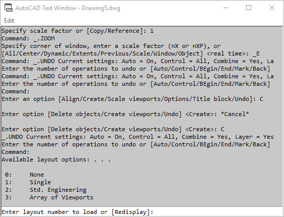
The routine will prompt you for the first point and second point if you desire to sketch your viewport. If you desire to use the "default" viewport size from the "mvsetup.dfs" file, then chose "Default" and press enter. The single viewport will appear to these coordinates define in the configuration file.


The next option I will choose is the "Scale viewports". The command first prompts you to select the viewport object. Press enter to continue.


There are numerous options for the control of the viewport but for this article I will leave the "MVSETUP" command at this point by pressing ESC.
Some of the short comings of the "MVSETP" command can be overcome by combining it with an AutoCAD macro which is available in AutoCAD. I will explain this process in a future article. The command can help make quick work of setting up your drawing so it is well worth the effort of first configuring the "mvsetup.dfs" file and using the command often.
No comments:
Post a Comment