Autodesk Fusion 360 drawing environment is still developing and sometimes you need certain critical drawing dimensions which, at this point, are not possible with the available functionality. In this short video, I will show you how to use model sketches to provide key points for the placement of a couple of these types of drawing dimensions.
Thursday, September 19, 2019

Tuesday, September 3, 2019
Creating Component Joints on Workplanes and Random Face Points Using Sketches
Autodesk Fusion 360 uses joints to add degrees of freedom between two components. I also use Autodesk Inventor which also uses assembly constraints to take away degrees of freedom between components. Assembly constraints allow you to use work planes for the jointing of components, joints do not. This is one feature I miss very much.
Recently I began to experiment with sketches on work planes as a method of allowing me to use Fusion 360 joints to joint components with work planes. In this short video I show you a very simple example of my process. I first of all show how to joint a components to a random point on the face of another component and then how to joint a component to a work plane all using a simple sketch. I used a simple offset work plane but any work plane can be use with the process.
I believe this will open up an entirely new method of assembling my models in Autodesk Fusion 360 and I hope you will find uses for the process also.
Recently I began to experiment with sketches on work planes as a method of allowing me to use Fusion 360 joints to joint components with work planes. In this short video I show you a very simple example of my process. I first of all show how to joint a components to a random point on the face of another component and then how to joint a component to a work plane all using a simple sketch. I used a simple offset work plane but any work plane can be use with the process.
I believe this will open up an entirely new method of assembling my models in Autodesk Fusion 360 and I hope you will find uses for the process also.
Wednesday, August 28, 2019
Measuring Between Holes in Autodesk Fusion 360
When you try and measure between the centers of holes, especially larger ones, it can be very frustrating trying to select the hole center. In this short video, I show you how to use the "Show Snap Points" option to make the job a snap.


Wednesday, July 10, 2019
Work Planes and Points Along a Path in Autodesk Fusion 360
The creation of work planes, for sketches, in the design of lofts in Autodesk Fusion 360 got a lot easier in the past few months with the introduction of the Plane Along a Path command located under the Construct drop-down menu. Along with the Point Along a Path command, modeling complex features sketches are a snap. Take a look at this short video and see just how easy placing complex work features along a path has become.


Sunday, June 30, 2019
Creating Custom Profile Coils in Autodesk Fusion 360
The Coil command in Autodesk Fusion 360 can only create four basic coil profiles. In my short video I show how to create a coil using any custom profile that does not intersect itself. The process is very intensive and Fusion 360 will act like it is locked up, be patient, it is only thinking.


Saturday, June 15, 2019
View Orbit in Autodesk Fusion 360
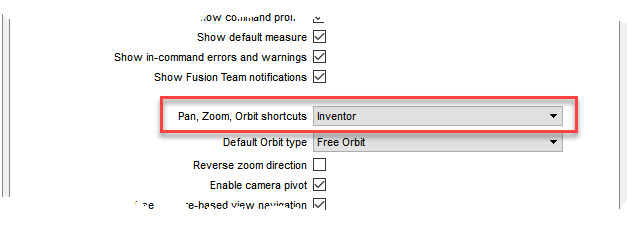
There are three methods you can use to orbit your model in Autodesk Fusion 360. If you have your Pan, Zoom, Orbit shortcuts set to "Inventor", you have a fourth method.
 In my short video, I cover these methods and explain options associated with each one.


Friday, March 22, 2019
Creating Conical Sheet Metal Components
Autodesk Fusion 360 does not provide a method for making conical sheet metal components but with the available tools and a little bit of surface work, the process can accomplished easily. In this short video I first create a simple sheet metal cone with its flat pattern. I then go back, in the timeline, and show you how to used the process to make a truncated cone that will produce a square edged flat pattern.
A special thanks to "TheCADWhisper", also known as "Top Daug" from the Fusion 360 forum for giving me inspiration into the methods outlined in this article.
UPDATE: Fusion 360 has added a new tool called Lofted Flange which makes the creation of a sheet metal cone very easy. In this video I go over the process of using this tool. If you desire to create an angled truncated cone, the process is also outlined in the video as it is a little different than the method outlined above.


Subscribe to:
Posts (Atom)