Sunday, October 16, 2016

Edit Inventor Sketch Coordinates

When you have an Inventor part sketch that has a dimension being referenced from a point that is not along the axis of the sketch, you will probably have to add a construction line to get the location dimension you desire.  In the example below the 120 mm dimension would be impossible if you did not add the construction line from the corner first.


There is a better way to handle this sketch.  You can move and rotate the sketch X,Y coordinate system, for this one sketch, to allow the placement of the required dimensions.  Below is the same sketch with the sketch coordinate system rotated to match the angled edge.  The same dimensions can be placed without the construction line.


One of the best features about using this method is that the sketch coordinate system is remembered for only the current sketch and will revert back to the part original sketch layout coordinates for any future sketches.  Since it is remembered, if you come back to this sketch, the sketch coordinate system is restored for any required editing.  I would like to step you through the process of establishing a new sketch coordinate system.  I will use the same model.  I will start by a new sketch on the face.  You will notice the original part orientation will place the sketch coordinates to match.

You will find the "Edit Coordinate System" tool under the Sketch tab on the Constrain panel in the drop down panel.


Inventor will prompt you to left click to select the existing origin.  Pick the small blue ball at the center of the existing sketch coordinate system.  The coordinate system will then be attached to your cursor so you can move it anywhere you desire.  Please note it will not actually physically float around but the "+" symbol beside your cursor arrow indicates that it is attached.


Next left click to select the point you want to be the new sketch origin.  I will be using the lower corner of the the angle cut for my example.  The sketch coordinate indicator will jump to the new location.


The next step is to align the desired sketch axis with the edge.  I will be using the X-axis.  Left click on top of the X-axis rod, not the arrowhead.  It will highlight as you pass over it to make sure you are ready to select it.


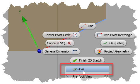
Next you want to left click to select the edge of the model you want to align the selected axis.  In my example I will select the angled model edge.  The sketch coordinate icon will align with the selected edge.  If it is flipped the wrong way simply right click and pick the "Flip Axis" command for the context menu.


The last step is to right click and select "OK" for the context menu or simple press the "Enter" key on the keyboard.  You will see the origin, X and Y axis shift to the new location.  The orientation of the sketch to the screen may be disturbing, but we will take care of that next.


The easiest way to re-orient the sketch so the sketch coordinate system is square to the screen is to select the "Look At" command located on the Navigation Panel and then pick the active sketch in the Inventor Browser.

Finish your sketch as you would normally do.  The next sketch you add to the part will follow the original sketch coordinate system.  If you edit this sketch, the modified sketch coordinate system will be restored.

You have to admit this is a very cool function to add your sketching ability and speed.

Wednesday, October 5, 2016

Let's Take a Look

In our digital age, we are often faced with having to find a viewer for an engineering file we have just received from another engineer, supplier or client.  In most cases we only need to view the file in order to see what a supplier is furnishing as the result of an order, comment on how a supplier has developed a component or any number of other reasons.  Most firms will only be using one or two different CAD applications and these are often not the ones other firms are using for component development.  Sure we can ask them to supply a native CAD version but sometimes users may not have any CAD applications installed to view it with.  Whatever the reason, we need a universal viewer that will get the job done quickly and give us insight on how a project is developing.

Autodesk is supplying such a free web based tool to the public.  It is called the Autodesk A360 Viewer and can be found at this address.   Autodesks only requirement to use this viewer is an Autodesk User ID which is also free which will unlock a few other free utilities as well.   If you do not have an Autodesk ID, you can sign up right here using your email address.


Once on the site, after you have signed,  you may want to see a list of all the design application file types it supports.  Click on the "2D and 3D formats supported" hyperlink to display the list, it is truly incredible!


 The next thing is to select the "Upload your design" icon and browse on your local workstation for the file you desire to view.  The application is pretty intelligent and will quiz you if it thinks that the file you have chosen requires other files to be uploaded as well to support it.  For example if you select an Inventor assembly (IAM) file, it requests the supporting part files (IPT)  to be uploaded as well.


 If you select an AutoCAD file, it will prompt you for any supporting files such as Xreference files.  If there are none, simply chose "No more files" to continue.

Once the upload starts, the viewer will begin to develop the 2D or 2D view.  If you do not want to wait, it tells you it will email you when it is finished and will give you a link to open your file view.


There is a note in the email that is important to read.  The Autodesk A360 Viewer requires a web browser that supports WebGL 3D graphics so Microsoft Internet Explorer is not a good choice.  I have used both Chrome and Firefox with great success.  The email will also give you a web address which you can send to others to view the file.  This ability can be also found on the A360 Viewer tools.

Once you are viewing the file, you will have a variety of tools to manipulate the model.  These are located at the bottom of the viewing screen.  They vary depending on the type of file, the 3D and 2D tool bars are shown below.


 Up at the top right of the viewing window are some standard tools for adding comments, getting a web link to the design to share with others, printing and taking a screenshot.  The most valuable one is to "Save to A360" if you are using this collaboration tool.

 
 One of the most interesting tools, found on both tool bars is the "Live Review" option.  When multiple reviewers are online, the live review can be executed.  It is only a textual exchange but it can be valuable to viewing group discussi0n.

One last thing I want to point out is that all designs placed on your Autodesk A360 Viewer page will be deleted after 30 days.  If you require a longer period you have the ability to request it by selecting the "Extend" icon located on the Recent Uploads page.  You can delete any old files by clicking on the three dots indicated below to display the "Delete" command.

 I cannot tell you how many times in the past I wish I had access to this viewer service especially one with so many tools and options.  Be sure to upload a file or two and take a look for yourself, you will be glad you did.
 

Thursday, September 22, 2016

Dragging in Inventor is Everywhere

In many Inventor command functions you have the opportunity to enter a function value or you can show Inventor the value by left clicking and "dragging" the displayed arrow.  In this article I hope to show you how to make this function as productive as possible.  Below is the extrusion command function that presents a "dragging" value entry.  You would simply left click the arrow and drag to the desired value.


Most all command functions which ask for a value also offer the drag arrow.  The commands cross both modeling and editing functions but depending on your configuration settings, you may not be getting the most from their use.  So I would like to talk about that first.  When I was a machine designer, my CAD manager told me to always design one, to use stock size materials when possible and two, when I had to machine cut material shoot for full inch dimensions, then halves and quarters of an inch.  He made it clear he did not want to see any eights or smaller of an inch unless it was necessary.  Of course we were a high tolerance machine builder and some dimensions had to be in the thousands of an inch and even ten thousands for special fits.  He believed using the largest inch division possible would speed shop production and I must say he was correct.  Just think how sending a piece of structural steel to the saw operator with a non-critical length as 36 47/64 inches instead of 36 3/4 inches would slow him down.  Sure he would probably cheat and round it but you never know.  

The configuration should be done in your companies part and assembly template files so it is available for all designs.  I will be using an inch part template but the same ideas applies to metric templates.  Open up the part template and on the Options panel under the Tools tab select Document Settings.


Select the Modeling tab in the Document Settings dialog box and enter your 3D Snap Spacing for both distance and angle dragging.  This will automatically keep the entry value to increments of the value you enter when you drag a function arrow.  In my case I have set 1/8 inch distance which will quickly give me enough accuracy for non-critical modeling but will also allow me to easily conform to my CAD manager rules just using the drag function, without keyboard entry.


I did not mention it but if you left click and drag on the ball at the base of the arrow, you can "drag" enter angle values in increments of the above setting, in my case 5 degrees.  This is not available in all functions.


Once you have saved your template, your next part or assembly model it will be easy to "drag" the value of your next extrusion, revolution or fillet radius just to mention a few functions.  Of course you can always over-ride the drag value by typing in an value you desire.


So that covers modeling functions but how about sketches.  You can accomplish the same thing in your Inventor sketches by configuring the Snap Spacing under the 2D Sketch section under the Sketch tab in the Document Settings dialog box.  Of course this should also be done in the part and assembly templates.  There is no setting for an increment angle.


There is one more configuration that needs to be set to allow 2D sketch snap spacing to work.  This is done in the Application Options dialog box located on the Options panel under the Tools tab.  On the Sketch tab, place a check mark beside the "Snap to grid" option.  You do not have to turn on the grid display, located in the same dialog box, unless you desire to have a visual grid during sketching.


You will get an odd readout when you are sketching lines at an angle if your Heads-Up-Display Dimension Input is set to "Polar Coordinates".  It is actually snapping to your snap settings but since it is on an angle, the values displayed are not intelligent.  If you change your Dimension Input to "Cartesian Coordinates", the values will display increments of your settings.  I do not believe this is an efficient setting but that is a personal opinion.

So give the Inventor dragging options a try.  If you would like to test before changing your default templates, make the configuration changes in one of your parts using your current template.  If you like them, transfer the settings to your default templates.

Friday, September 16, 2016

Creating a Material Cut List for Your Inventor Drawings

In this article I will be developing a Material Cut List to automatically report cut lengths for common materials used in Inventor.  I will be developing this for one drawing and will not go into the process of editing the project design data and templates to make it available for all drawings.  The process is the same for the most part, only the method of saving the design data will not be covered.  I will be using an Inventor IDW drawing format but the process is identical if your company uses the Inventor DWG drawing format.

Normally cut sizes are applicable to four Inventor standard components.  These are:


  • Sheet Metal Flat Sheet Extents
  • Content Center Standard Structural Shapes such as angles, channel, and tubing
  • Hose lengths either from a routing assembly or lengths used directly in a design
  • Pipe and Tubing lengths also from a routing assembly or lengths used directly in a design
Below is my example drawing with one of each standard component.  I have use both a pipe and tube section just to illustrate.  The Material Cut List is the same for both so if you configure for one you will be set for the other automatically.


Keep in mind that the format of the cut lengths and the column headers are fully configurable, you are not restricted to my selections.

The first place to start is to configure your Inventor part template to capture three properties of sheet metal parts, the Sheet Metal Rule which will report to the stock number column, the sheet metal flat pattern width and length.  These configurations are added to your sheet metal template as custom properties.  These custom properties are set to report standard sheet metal properties.  Below I show the custom properties with my chosen names, yours can be anything you desire.  Please note each one is has a function for its value.  SML stands for the sheet metal flat length, SMW the sheet metal flat width and the Sheet Metal Style will report the name of my sheet metal rule which is my material description.  


After selecting an iProperty the value function can be edited using the icon marked with the red arrow.  The initial entry is typed directly into the value box.  The three iProperties and their value functions are:  (the equal sign is a part of the value function.)
  • SML  =<Sheet Metal Length>
  • SMW =<Sheet Metal Width>
  • Sheet Metal Style =<Sheet Metal Rule>
Enter and save these in your Inventor sheet metal template and you are all set.  The Inventor custom iProperty value for structural sections, pipe, hose and tubing are entered automatically during component placement so no modification to your part template is required.  The custom iProperty name for each is listed below.
  • Structural Sections - G_L
  • Pipe, hose and tubing - PL
The next configuration to to develop a Material Cut List in your Inventor drawing template.  Open up your drawing template and select "Styles Editor" under the Manage tab in the Styles and Standards panel.


Make sure that your are editing your company Design Data standard, expand the "Parts List" entry and right click to on the title to create a new parts list style called Material Cut List.  

Next fill in the title, select the desired text styles and choose other appearance settings to suit your company standards.  The main configuration is to select "Column Chooser" which will allow you to choose what Inventor iProperties to report in the Material Cut List.  

Some of the iProperties are listed in the "Available Properties" table but all custom iProperties are not and you must enter them using the "New Property" icon.  Remember to add the exact custom iProperty name, not what you want the Material Cut List column will eventually read, this is added later.  For example, one of my custom iProperties is PL so this is what I enter in the Define New Property dialog box.


Continue until you  have all the iProperities added then select "OK" to return to the configuration table editor.  You will notice all the selected and entered iProperties are shown in the list.


The next step is to click on each column header and edit the name to whatever value you would like to appear in the finished placed Material Cut List on the drawing.  Keep in mind that names will word wrap if they exceed the column width which is entered in the next column.  You may have to practice with column widths to decide which is best for you.  You can always resize the list after is is placed on the drawing but it is not desirable. 

The next step is to right click on each Property and select "Format Column".  I will start with the Stock Number Property.


The only change I need here is for the Stock Number to report the custom iProperty Sheet Metal Style if it exists.  This is accomplished on the Substitution tab as shown below.


The G_L property has two changes, one to configure the column units format and the value column justification.

The second in to enable value substitution if the component is not a structural component but a pipe, tube or hose.  We would like the PL iPropety value to replace the G_L value if this is the case.  Also you will need to configure the units formatting to use if the substitution occurs.

You will need to configure the last two properties using the Column Format tab to set units display and data justification following the same process used earlier.  When finish, select "Save and Close" to save the changes to the drawing template.  I want again to remind you that I am only configuring the Material Cut List in this drawing, if you are configuring for all drawings, these configuration settings must be exported to the company Inventor design data and template files.

Once you have your drawing view created, you now want to place the Material Cut List.  The placement is accomplished by selecting  "Parts List" command under the Annotate tab and then selecting Material Cut List from the Format drop down.  The process from this point is the same as if you were placing a parts list in the drawing.


One last note, if you have configured your Material Cut List to report sheet metal flat pattern extents you must have developed a flat pattern to have the values populate.  Enjoy!

Monday, September 5, 2016

I Installed the Vault Client, Where is My AutoCAD Vault Add-in Ribbon Tab?

You have installed the Autodesk Vault Client it seems without a hitch.  You open up AutoCAD and the Vault tab is missing.  You scratch your head and wonder what when wrong? 


Take heart, it usually is something very simple.  From this point on, you must be an Administrator of the workstation you are working on.  The first thing to check is if you configured the Vault Client installation to add the Vault Add-in for AutoCAD.  Make sure you close all running programs and go to the Windows Control Panel.  Select "Programs and Features" from the list.  Please note that I have configured my Control Panel for small icons which makes it easier to find.

After the installed Programs and Features have fully loaded, browse down to the Vault Client installation for your version.  In my case I have installed Autodesk Vault Professional 2017 (Client).


Right click on the entry and left click the "Uninstall/Change" option.  Don't worry, you have to choose another option later on if you are uninstalling the application.  Once the application installation routine has loaded, left click the "Add or Remove Features" icon.


The Vault Client feature list will appear.  Look at the list carefully, it represents all the applicable Autodesk applications installed on your workstation that can be configured with the Vault Client Add-in.  In my example, the "AutoCAD 2017 Add-in" is not checked which in turn did not install the necessary AutoCAD Vault Tab.  This could have occurred for two main reasons.  The Autodesk Vault Client was installed "before" the Autodesk AutoCAD application or someone unchecked it during installation.  Left click in the small box to place a check mark.  Select "Update" in the lower right hand corner of the dialog box to continue.  NOTE: If there already is a check mark, skip this step and select "Cancel" at the bottom right side of the dialog box and read on.


Occasionally you will be presented with the following dialog box which is requesting the location of the Vault installation files.  You may have to seek the help of your system administrator as to the files location and then simply use the "Browse" icon to locate it and then press "OK" to continue.


Once the screen informing you that the product was successfully upgraded, select the "Finish" icon to close the application.  Also close the Windows Control Panel.  Next run your AutoCAD application.  Sometimes the Vault Add-in will load up and the Vault tab will appear and you are finished.  If it still does not appear, you have one more step to execute.  Open a new drawing using any template your desire and type "CUILOAD" on the screen and then press "Enter".

This will bring up Load/Unload Customizations dialog box.  The listing at the top are the currently loaded AutoCAD user menus (called customizations).  You will notice that the "Vault" entry is missing.  Select the "Browse" icon at the bottom of the dialog box to continue.


Browse in the folder C:\Users\<current user>\AppData\Roaming\Autodesk\AutoCAD <version>\R<release>\enu\support (normally the default folder) and select the "VaAc.cuix" file.  Select "Open" to continue.


Back in the Load/Unload Customizations dialog box, select the "Load" icon to add it to the Loaded Customization Groups list.  Select "Close" to finish.


At this point, you should have a new "Vault" tab on your AutoCAD ribbon and you are ready to go.