
Monday, January 30, 2017
Inventor Solid Body Modeling
Autodesk Inventor has a marvelous tool called Solid Body Modeling or it is sometimes called Multi-Body Modeling. I created a video showing how I can use this modeling method to create a male and female die for a plastic shell part supplied to me in a SAT format. I then continued to show how to create the plastic shell part if you only had the male and female die using Multi-Body Modeling. Click on this link to access the video.


Friday, January 20, 2017
My 10 Favorite Inventor Sketching Tips
I have published a video of my favorite 10 Autodesk Inventor sketching tips on YouTube. There are a lot more but I tried to limit the video to 15 minutes. I hope you will find some useful in your Inventor design work. Please click here to be taken to video.
Monday, January 16, 2017
Using Autodesk A360 Drive for Collaborative Design - Part 3
Welcome back to part 3 of the article describing the features of Autodesk A360 Drive. If you missed part 1 and part 2, simply click on the part you missed for a review. I want to cover the main feature, and probably the reason it exists, of A360 Drive in this article. Autodesk A360 Drive is a collaboration site where the poster of models can invite others to view, download and comment on designs. Depending on the share permissions the owner of the site grants to other users will determine what functions or features are available.
The first task of the owner is to "Share" some or all the files on A360 Drive with others. This is done using the share function. This function can be found on the "Home" view which is where all folders and files appear. If you select "Share" on the folder level, all files contained in the folder will be given the same share permissions. If you select "Share" on the file level, only that one file will have the granted share permissions. This is why in part 2 of this article I recommended you place files in folders so you can share all files in one click. I will be sharing my folder "Right Angle Engine" with my second account which uses my middle and last name in order to show the features. I first select the folder by hovering over the share symbol beside the folder.
 Selecting the "Share" icon will allow you to add email addresses and give the desired rights to the entire group you are inviting. If you desire to give each email address different rights, you will have to execute the "Share" function multiple times.
 The recipient will receive an email similar to the one below. Please note the email message include your invitation message as well as a link to the files in the folder which was shared.

Full Access rights will give the recipient the ability to re-share the complete folder with others so be careful before giving this high level of access to your folders and files. If the recipient has been given "Full Access", they will have the right to send a view link to any individual file shared with them to anyone else. Also they will have the right to allow downloading of the individual file as well. The link will be created from A360 Drive, sent to the recipient by email and the recipient can click on the link and view the file online in Autodesk A360 Viewer.

If the "View and Download" permission has been given during the share, the recipient can download any file to their local drive. One great thing about A360 Drive is the download of the complete folder will automatically zip the entire contents to a folder on the recipient's computer.
 During the collaboration effort, comments can be made directly inside the file viewer. The icon is located in the upper right hand corner of the viewer window. Anyone who receives a share from the owner will have comment ability.
 Comments are cumulative and will remain during the share folder life. The ability to reply to specific messages is available. One feature I did not see is a visual or email notification that new comments have been added.
 The last feature I would like to mention is the version handling ability of A360 Drive. If you are the owner you have two ways to upload a new version of any file. The first is to simply copy a new version to your A360 local drive and replace the existing files. A360 will automatically upload and version the corresponding files on A360 Drive. If you are not the owner, you must select the file(s) you want to version and select "Upload New Version". The owner can use this method as well.
 Once A360 Drive processes the version change it will display the newest version automatically and indicated which version is displaying. Another great feature is the ability to select which version is displayed for design comparisons.
 There are a few other features I hope you will explore on your own. You have the ability to "Move" files to a folder of your choice on A360 Team which makes it handy if this application is used by your team. A360 Drive has a trash bin so if a file or folder is deleted by accident, it can be recovered. Do not forget to empty it once in awhile because you only have 5 GB free space. Files may be copied within A360 Drive making it convenient to create new collaborative projects.
Please give Autodesk A360 Drive a try, you will be glad you did.
The first task of the owner is to "Share" some or all the files on A360 Drive with others. This is done using the share function. This function can be found on the "Home" view which is where all folders and files appear. If you select "Share" on the folder level, all files contained in the folder will be given the same share permissions. If you select "Share" on the file level, only that one file will have the granted share permissions. This is why in part 2 of this article I recommended you place files in folders so you can share all files in one click. I will be sharing my folder "Right Angle Engine" with my second account which uses my middle and last name in order to show the features. I first select the folder by hovering over the share symbol beside the folder.


Full Access rights will give the recipient the ability to re-share the complete folder with others so be careful before giving this high level of access to your folders and files. If the recipient has been given "Full Access", they will have the right to send a view link to any individual file shared with them to anyone else. Also they will have the right to allow downloading of the individual file as well. The link will be created from A360 Drive, sent to the recipient by email and the recipient can click on the link and view the file online in Autodesk A360 Viewer.

If the "View and Download" permission has been given during the share, the recipient can download any file to their local drive. One great thing about A360 Drive is the download of the complete folder will automatically zip the entire contents to a folder on the recipient's computer.


Please give Autodesk A360 Drive a try, you will be glad you did.
Using Autodesk A360 Drive for Collaborative Design - Part 2
I apologize of taking so long to get to part 2 of this article where I talk about the features when working inside Autodesk A360 Drive, so let's get started.
I will be using my second method of adding an Inventor assembly with all supporting files which I think is the most productive method of using A360 Drive. If you need a refresher, see Part 1 of this article. The first recommendation is to place all files in a folder structure. Some of the functions within A360 Drive can only be applied to a group of files by selecting a folder, unless you enjoy selecting one file at a time and then applying the function. In the following graphic I show one folder, which is selected, which in turn selects each file contained within.
 Next I would like to take a look at the functions available when viewing a file. I will be viewing an Inventor assembly. Selecting the folder, Right Angle Engine, you will be taken to the list of Inventor files. I will select the assembly file and this will open the A360 Drive viewer. At the bottom you will see various tools which are labeled below.

I will be using my second method of adding an Inventor assembly with all supporting files which I think is the most productive method of using A360 Drive. If you need a refresher, see Part 1 of this article. The first recommendation is to place all files in a folder structure. Some of the functions within A360 Drive can only be applied to a group of files by selecting a folder, unless you enjoy selecting one file at a time and then applying the function. In the following graphic I show one folder, which is selected, which in turn selects each file contained within.


- Orbit - This function operates identical to the Inventor Orbit function. Using your left mouse button drag while hovering near various locations on the compass, you can achieve different obit motions. Do not forget about the model centering feature by left clicking on a model location to make it the pivot of the orbit. Of course after you really mess it up, you can return to "Home" position by selecting the "Home" icon in the upper right corner of the viewing window. By the way, the orbit command is automatically engaged when you enter the viewing window, you just do not have all the controls the actual Orbit command offers. To deselect the Orbit command, select the command again or press ESC on the keyboard. This applies to all the commands.
- Pan - This function allows you to hold down your left button and pan the model in any direction. You can skip this command by holding down your middle mouse button. I you do not have a middle mouse button hold down the Shift key and the left mouse button to perform the same function. The right mouse button works also.
- Zoom - Selecting this command allows you to use your left mouse button drag to zoom your model. You can do the same thing using the wheel on your mouse if available.
- First Person - This allows you to use the keyboard for viewing the model instead of using a mouse. The keys are defined on-screen as soon as you select the command.
- Camera Interactions - This command has three options, Fit to View, Roll and Focal Length. Select the command then close to the small up arrow to change the option.
- Section Views - This command has four model sectioning options, X, Y, Z axis and Box. Select the command and then close to the small up arrow to change the sectioning option. Leaving the command by selection it a second time or pressing ESC returns the model to a non-sectioned state. One thing about the Box option I did not care for is that you can only "size" the box in one axis.
- Measure - By selecting two objects the measurement is returned. This is meant for measurement estimates, not accuracy so be aware of your results.
- Explode Model - Selecting this command will present a slider bar. Dragging the slider with your left mouse will explode an assembly components. This function will of course not work when viewing a single assembly component.
- Properties - This function is of little value when viewing a model. It reports the name of the component or assembly which you already know from the file name you selected to open the view. Properties will be covered later in this article.
- Settings - This function opens a dialog box with two tabs, Navigation and Selection settings and Performance and Appearance settings. One particular setting you will want to use immediately is under the Performance and Appearance tab. The Environmental and Lighting selection drop down will enable you to adjust the colors and intensity of the lighting for better viewing. I would suggest using the "Plaza" selection which I found to be the best. The viewer does a very poor job of representing true model colors.
- Full Screen - This functions just as it is named. Use ESC to return to the normal viewing window.
If you have selected the setting to show the View Cube, it functions exactly like the view cube in Inventor. You will find the View Cube options appear below and to the right of the view cube when you hover over it. The default view is perspective and even after you change it, it will return when the viewing window is open again.

When viewing an Inventor assembly, one of the most valuable tools is the Scenes button in the upper left corner of the viewing screen. Selecting it will expand the assembly into a list of its components. By selecting one or more (using the Shift key) you can hide all other components for detail viewing. To return all hidden components either press ESC or right click in the background and select "Show All Objects". The most valuable feature of this process is selecting the "Properties" function when only one component is showing. The full Inventor iProperties are displayed. The "Other" iProperties are the custom iProperties of the component. the iProperty is not displayed unless it has a value.

This article is getting pretty long and I have a lot more to mention so I will continue in Part 3 of this article. I promise it will not be as long as the time between Part 1 and Part 2.


This article is getting pretty long and I have a lot more to mention so I will continue in Part 3 of this article. I promise it will not be as long as the time between Part 1 and Part 2.
Saturday, November 5, 2016
Using Autodesk A360 Drive for Collaborative Design - Part 1
When installing Autodesk Product Design Suite 2017, one optional application which can be configured is the A360 Desktop which will install a local A360 Drive also. This application will create a synchronized link between the local A360 Drive and the Autodesk A360 Drive website. Using your Autodesk ID, which can be obtained free, you can log into the A360 Drive website to manage your uploaded files, share access with others for collaborative design and update your files as design changes are made.

In this article I will be using Inventor design files but any type file can be added to the A360 Drive website and shared with team members. When Inventor 2017 is installed an add-in is installed called Connected Design on A360.
 If this add-in is loaded and the Connected Design on A360 user interface is enabled, there will be a new small icon added to your Inventor graphics screen in the lower right hand corner. This icon, when selected, will give you access directly to the Autodesk A360 Drive and also allow you to upload collaboration files directly from the currently open part or assembly model.

 If you select this small icon it will open up the Connected Design on A360 panel.

The panel consists of two main tabs, Events and Design Shares. If you currently do not have any designs currently on your Autodesk A360 Drive, this tab will be grayed out. If you would like to quickly open and log into your Autodesk A36 Drive, you can select the A360 Drive icon in the upper left hand corner.
 To get started sharing a part or assembly model on A360 Drive, open a part or assembly model in Inventor and then select the Design Share this View at the bottom of the panel. After selection you have the ability to change and add to the Design Share file name, add comments, decide to share Component Names and/or Part Properties and add the email of Collaborators who you desire to be notified via email of the shared design. Later you can also collaborators inside the Autodesk A360 Drive website. Selecting the Start Design Share button at the bottom of the dialog box will add the file to the website.

 Once the design has be shared to the A360 Drive website, the Design Shares tab will become active. On this panel you will see shares you own, be able to add email addresses to invite collaborators and will see design shares shared with you. You can also end design shares you have uploaded. At the bottom of the dialog box you can see the design share upload status.

I am sure you will notice that the application created a single file for my uploaded assembly. This means the assembly model and part models are combined into this single file and individual files are not available for download. This feature makes sure that the design is secure and proprietary content is protected. If someone downloads the file, it has a .collaboration extension and is not editable.
In this article I will not cover the functions available on the A360 Drive website, I will do that in a future post. I would like to focus on other ways to use the local A360 Drive and A360 Drive website. As I just explained, the collaboration file created by Inventor is non-editable which is not what some design teams desire. There are those you want to share editable files between design teams around the world. The A360 Desktop application not only creates a A360 Drive on your system but also installed the controlling A360 Desktop application which you can find in the running application on the Windows taskbar. By default, the application starts when you Windows starts.

If you would like to share any files on the A360 Drive website, all you have to do is copy them into the local A360 Drive. The application will automatically synchronize all files from the local A360 Drive to the A360 Drive website. I suggest that you do not save files directly from the CAD application to the local A360 Drive due to the fact is will be outside of the current Inventor project file and will create a uncontrolled saved file location. When copying an Inventor assembly, it is unnecessary copy the associated part files because the application will automatically ask you if you desire to upload all associated files.

If you desire to skip this dialog box and have all associated files uploaded automatically, right click on the A360 Drive icon on the taskbar and select preferences.

In the A360 Desktop Preferences panel select "Copy Automatically" radio button under Linked files. When you now copy an Inventor assembly all associated files will be copied to the local A360 Drive folder and will be automatically synchronized with the A360 Drive website. I know I am talking about Inventor files here but if you copy an AutoCAD drawing containing Xreferences, they will be copied as well to the local A360 Drive.

Synchronization can be controlled by selections within the A360 Desktop icon in the taskbar if desired. Right click on the icon to see the options.

If you look at the copied files, in your local A360 Drive, you will see the synchronization status indicated in the file icons.
 As the design changes, simply copy the edited file to your local A360 Drive and the automatic synchronization will add a version to the existing A360 Drive website file retaining the previous version to aid in collaborative reviewing.
In this article I have covered two methods of sharing Inventor designs on the Autodesk A360 Drive website. One uses a strictly view able file which cannot be downloaded and edited and the other method will place editable files on the website which can be downloaded by anyone you have invited to collaborate with your design on the A360 Drive website. I will use the next article to review some of the options available on the A360 Drive website.

In this article I will be using Inventor design files but any type file can be added to the A360 Drive website and shared with team members. When Inventor 2017 is installed an add-in is installed called Connected Design on A360.


I am sure you will notice that the application created a single file for my uploaded assembly. This means the assembly model and part models are combined into this single file and individual files are not available for download. This feature makes sure that the design is secure and proprietary content is protected. If someone downloads the file, it has a .collaboration extension and is not editable.
In this article I will not cover the functions available on the A360 Drive website, I will do that in a future post. I would like to focus on other ways to use the local A360 Drive and A360 Drive website. As I just explained, the collaboration file created by Inventor is non-editable which is not what some design teams desire. There are those you want to share editable files between design teams around the world. The A360 Desktop application not only creates a A360 Drive on your system but also installed the controlling A360 Desktop application which you can find in the running application on the Windows taskbar. By default, the application starts when you Windows starts.
If you would like to share any files on the A360 Drive website, all you have to do is copy them into the local A360 Drive. The application will automatically synchronize all files from the local A360 Drive to the A360 Drive website. I suggest that you do not save files directly from the CAD application to the local A360 Drive due to the fact is will be outside of the current Inventor project file and will create a uncontrolled saved file location. When copying an Inventor assembly, it is unnecessary copy the associated part files because the application will automatically ask you if you desire to upload all associated files.

If you desire to skip this dialog box and have all associated files uploaded automatically, right click on the A360 Drive icon on the taskbar and select preferences.
In the A360 Desktop Preferences panel select "Copy Automatically" radio button under Linked files. When you now copy an Inventor assembly all associated files will be copied to the local A360 Drive folder and will be automatically synchronized with the A360 Drive website. I know I am talking about Inventor files here but if you copy an AutoCAD drawing containing Xreferences, they will be copied as well to the local A360 Drive.

Synchronization can be controlled by selections within the A360 Desktop icon in the taskbar if desired. Right click on the icon to see the options.
If you look at the copied files, in your local A360 Drive, you will see the synchronization status indicated in the file icons.

In this article I have covered two methods of sharing Inventor designs on the Autodesk A360 Drive website. One uses a strictly view able file which cannot be downloaded and edited and the other method will place editable files on the website which can be downloaded by anyone you have invited to collaborate with your design on the A360 Drive website. I will use the next article to review some of the options available on the A360 Drive website.
Sunday, October 16, 2016
Edit Inventor Sketch Coordinates
When you have an Inventor part sketch that has a dimension being referenced from a point that is not along the axis of the sketch, you will probably have to add a construction line to get the location dimension you desire. In the example below the 120 mm dimension would be impossible if you did not add the construction line from the corner first.


One of the best features about using this method is that the sketch coordinate system is remembered for only the current sketch and will revert back to the part original sketch layout coordinates for any future sketches. Since it is remembered, if you come back to this sketch, the sketch coordinate system is restored for any required editing. I would like to step you through the process of establishing a new sketch coordinate system. I will use the same model. I will start by a new sketch on the face. You will notice the original part orientation will place the sketch coordinates to match.
 You will find the "Edit Coordinate System" tool under the Sketch tab on the Constrain panel in the drop down panel.

Inventor will prompt you to left click to select the existing origin. Pick the small blue ball at the center of the existing sketch coordinate system. The coordinate system will then be attached to your cursor so you can move it anywhere you desire. Please note it will not actually physically float around but the "+" symbol beside your cursor arrow indicates that it is attached.

Next left click to select the point you want to be the new sketch origin. I will be using the lower corner of the the angle cut for my example. The sketch coordinate indicator will jump to the new location.

The next step is to align the desired sketch axis with the edge. I will be using the X-axis. Left click on top of the X-axis rod, not the arrowhead. It will highlight as you pass over it to make sure you are ready to select it.

Next you want to left click to select the edge of the model you want to align the selected axis. In my example I will select the angled model edge. The sketch coordinate icon will align with the selected edge. If it is flipped the wrong way simply right click and pick the "Flip Axis" command for the context menu.


The last step is to right click and select "OK" for the context menu or simple press the "Enter" key on the keyboard. You will see the origin, X and Y axis shift to the new location. The orientation of the sketch to the screen may be disturbing, but we will take care of that next.

The easiest way to re-orient the sketch so the sketch coordinate system is square to the screen is to select the "Look At" command located on the Navigation Panel and then pick the active sketch in the Inventor Browser.
 Finish your sketch as you would normally do. The next sketch you add to the part will follow the original sketch coordinate system. If you edit this sketch, the modified sketch coordinate system will be restored.
You have to admit this is a very cool function to add your sketching ability and speed.

There is a better way to handle this sketch. You can move and rotate the sketch X,Y coordinate system, for this one sketch, to allow the placement of the required dimensions. Below is the same sketch with the sketch coordinate system rotated to match the angled edge. The same dimensions can be placed without the construction line.


Inventor will prompt you to left click to select the existing origin. Pick the small blue ball at the center of the existing sketch coordinate system. The coordinate system will then be attached to your cursor so you can move it anywhere you desire. Please note it will not actually physically float around but the "+" symbol beside your cursor arrow indicates that it is attached.

Next left click to select the point you want to be the new sketch origin. I will be using the lower corner of the the angle cut for my example. The sketch coordinate indicator will jump to the new location.

The next step is to align the desired sketch axis with the edge. I will be using the X-axis. Left click on top of the X-axis rod, not the arrowhead. It will highlight as you pass over it to make sure you are ready to select it.

Next you want to left click to select the edge of the model you want to align the selected axis. In my example I will select the angled model edge. The sketch coordinate icon will align with the selected edge. If it is flipped the wrong way simply right click and pick the "Flip Axis" command for the context menu.

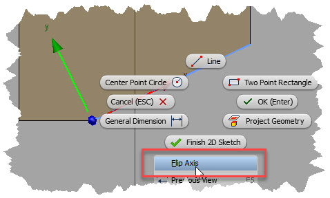
The last step is to right click and select "OK" for the context menu or simple press the "Enter" key on the keyboard. You will see the origin, X and Y axis shift to the new location. The orientation of the sketch to the screen may be disturbing, but we will take care of that next.

The easiest way to re-orient the sketch so the sketch coordinate system is square to the screen is to select the "Look At" command located on the Navigation Panel and then pick the active sketch in the Inventor Browser.
You have to admit this is a very cool function to add your sketching ability and speed.
Wednesday, October 5, 2016
Let's Take a Look
In our digital age, we are often faced with having to find a viewer for an engineering file we have just received from another engineer, supplier or client. In most cases we only need to view the file in order to see what a supplier is furnishing as the result of an order, comment on how a supplier has developed a component or any number of other reasons. Most firms will only be using one or two different CAD applications and these are often not the ones other firms are using for component development. Sure we can ask them to supply a native CAD version but sometimes users may not have any CAD applications installed to view it with. Whatever the reason, we need a universal viewer that will get the job done quickly and give us insight on how a project is developing.
Autodesk is supplying such a free web based tool to the public. It is called the Autodesk A360 Viewer and can be found at this address. Autodesks only requirement to use this viewer is an Autodesk User ID which is also free which will unlock a few other free utilities as well. If you do not have an Autodesk ID, you can sign up right here using your email address.

Once on the site, after you have signed, you may want to see a list of all the design application file types it supports. Click on the "2D and 3D formats supported" hyperlink to display the list, it is truly incredible!

The next thing is to select the "Upload your design" icon and browse on your local workstation for the file you desire to view. The application is pretty intelligent and will quiz you if it thinks that the file you have chosen requires other files to be uploaded as well to support it. For example if you select an Inventor assembly (IAM) file, it requests the supporting part files (IPT) to be uploaded as well.

If you select an AutoCAD file, it will prompt you for any supporting files such as Xreference files. If there are none, simply chose "No more files" to continue.
 Once the upload starts, the viewer will begin to develop the 2D or 2D view. If you do not want to wait, it tells you it will email you when it is finished and will give you a link to open your file view.

There is a note in the email that is important to read. The Autodesk A360 Viewer requires a web browser that supports WebGL 3D graphics so Microsoft Internet Explorer is not a good choice. I have used both Chrome and Firefox with great success. The email will also give you a web address which you can send to others to view the file. This ability can be also found on the A360 Viewer tools.
Once you are viewing the file, you will have a variety of tools to manipulate the model. These are located at the bottom of the viewing screen. They vary depending on the type of file, the 3D and 2D tool bars are shown below.


Up at the top right of the viewing window are some standard tools for adding comments, getting a web link to the design to share with others, printing and taking a screenshot. The most valuable one is to "Save to A360" if you are using this collaboration tool.

One of the most interesting tools, found on both tool bars is the "Live Review" option. When multiple reviewers are online, the live review can be executed. It is only a textual exchange but it can be valuable to viewing group discussi0n.
 One last thing I want to point out is that all designs placed on your Autodesk A360 Viewer page will be deleted after 30 days. If you require a longer period you have the ability to request it by selecting the "Extend" icon located on the Recent Uploads page. You can delete any old files by clicking on the three dots indicated below to display the "Delete" command.
 I cannot tell you how many times in the past I wish I had access to this viewer service especially one with so many tools and options. Be sure to upload a file or two and take a look for yourself, you will be glad you did.
Autodesk is supplying such a free web based tool to the public. It is called the Autodesk A360 Viewer and can be found at this address. Autodesks only requirement to use this viewer is an Autodesk User ID which is also free which will unlock a few other free utilities as well. If you do not have an Autodesk ID, you can sign up right here using your email address.

Once on the site, after you have signed, you may want to see a list of all the design application file types it supports. Click on the "2D and 3D formats supported" hyperlink to display the list, it is truly incredible!

The next thing is to select the "Upload your design" icon and browse on your local workstation for the file you desire to view. The application is pretty intelligent and will quiz you if it thinks that the file you have chosen requires other files to be uploaded as well to support it. For example if you select an Inventor assembly (IAM) file, it requests the supporting part files (IPT) to be uploaded as well.

If you select an AutoCAD file, it will prompt you for any supporting files such as Xreference files. If there are none, simply chose "No more files" to continue.


There is a note in the email that is important to read. The Autodesk A360 Viewer requires a web browser that supports WebGL 3D graphics so Microsoft Internet Explorer is not a good choice. I have used both Chrome and Firefox with great success. The email will also give you a web address which you can send to others to view the file. This ability can be also found on the A360 Viewer tools.
Once you are viewing the file, you will have a variety of tools to manipulate the model. These are located at the bottom of the viewing screen. They vary depending on the type of file, the 3D and 2D tool bars are shown below.


Up at the top right of the viewing window are some standard tools for adding comments, getting a web link to the design to share with others, printing and taking a screenshot. The most valuable one is to "Save to A360" if you are using this collaboration tool.

One of the most interesting tools, found on both tool bars is the "Live Review" option. When multiple reviewers are online, the live review can be executed. It is only a textual exchange but it can be valuable to viewing group discussi0n.

Subscribe to:
Posts (Atom)